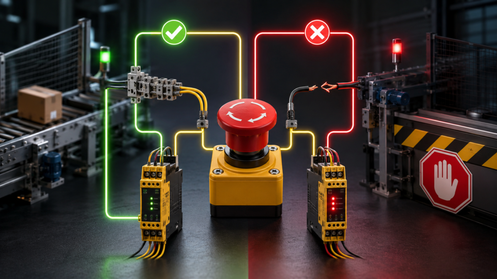
An emergency-stop button spends almost its entire life doing nothing.
It sits on the machine, bright red, waiting. The production line runs, the conveyor moves, and the operator may not touch that button for months. Hopefully never.
Yet the circuit connected to it must remain trustworthy every second.
That is why emergency-stop circuits commonly use normally closed contacts rather than normally open ones. In the machine’s healthy operating state, the safety circuit is complete and current flows through the emergency-stop contact. Pressing the button opens that circuit and commands the machine to stop.
More importantly, a broken wire can produce the same result.
The machine sees the loss of the safety signal as a fault instead of quietly assuming that everything is fine. This is a basic example of fail-safe design: when something goes wrong with the control circuit, the system should move toward a safer condition rather than continue operating unnoticed.
Simple idea. Very important consequences.
What Does “Normally Closed” Actually Mean?
The word normally describes the contact’s state when the device is not being operated.
For an emergency-stop button:
- Normally closed contact: closed when the button is released and healthy.
- Normally open contact: open when the button is released and healthy.
When the emergency-stop button is pressed, the normally closed contact opens.
This interrupts the safety circuit. A safety relay, safety PLC or contactor-control circuit detects that interruption and removes permission for hazardous machine movement.
The word “normal” does not mean the machine is running. It refers only to the mechanical resting state of the contact.
That distinction confuses beginners fairly often.
The Circuit Is Energised to Allow Operation
A typical emergency-stop circuit follows an energise-to-run principle.
The machine is allowed to operate only while the safety circuit is complete and healthy. Current must pass through the emergency-stop contacts, guard switches and other safety devices before the machine receives a run-permission signal.
When everything is healthy:
- the emergency-stop button is released;
- its normally closed contacts are closed;
- the safety circuit is complete;
- the safety relay can energise;
- the machine may be permitted to operate.
When the button is pressed:
- the normally closed contact opens;
- current through the safety input disappears;
- the safety relay drops out;
- its safety outputs open;
- contactors, drives or other final switching devices are commanded into the required safe state.
The machine must continuously prove that the safety loop is intact.
It does not receive permission simply because nobody has reported a problem.
How a Broken Wire Becomes a Detectable Fault
Imagine an emergency-stop circuit built with a normally open contact.
During ordinary operation, that contact would remain open. No current would flow through the wiring. Pressing the button would close the contact and send a stop signal.
That sounds workable—until the wire breaks.
With a normally open arrangement, a broken conductor may look exactly like the normal unpressed condition. The circuit was open before the break, and it remains open afterwards.
Nothing changes at the controller.
The operator may later press the emergency-stop button, but the signal cannot travel through the broken wire. The machine continues operating because the fault remained invisible until the exact moment the safety function was needed.
That is a nasty design.
Now consider a normally closed circuit.
During normal operation, current flows continuously through the contact and wiring. If a conductor breaks, a terminal becomes loose or the button is disconnected, the circuit opens.
The safety controller detects the loss of current and responds as though the emergency-stop button had been pressed.
The machine stops, and restarting should be prevented until the circuit is restored and properly reset.
The broken wire therefore announces itself.
This Is the Heart of Fail-Safe Design
Fail-safe design does not mean that a system can never fail.
No component is immortal. Wires break, contacts wear, relays stick and people occasionally connect things in creative ways that were not shown in the schematic.
Fail-safe design means that predictable failures are arranged to produce a safe response whenever reasonably possible.
For an emergency-stop loop, loss of electrical continuity is a predictable fault. Using normally closed contacts turns that loss into a stop command.
The healthy state requires something active and verifiable: a complete circuit.
The failed state removes permission.
That is far better than designing the machine so it continues running whenever the controller becomes uncertain.
In safety systems, uncertainty should rarely earn a cheerful “carry on.”
Why the Emergency-Stop Contact Opens the Circuit
A control system could theoretically monitor many different signal patterns, but opening a circuit has practical advantages.
Removing current can:
- de-energise relay coils;
- switch off contactor coils;
- remove drive-enable signals;
- open safety outputs;
- trigger a safety PLC input;
- interrupt pneumatic or hydraulic control commands.
Many safety functions therefore use a de-energisation principle. A healthy circuit keeps the safety devices energised. Pressing the emergency stop removes that energy.
If control power fails entirely, the safety relay also drops out.
This does not guarantee that every possible source of hazardous energy disappears instantly, but it prevents the control circuit from relying on electrical power to maintain the stop command.
A relay that must remain energised for the machine to run naturally falls into the off state when its supply disappears.
Gravity, springs and de-energised contactors do a surprising amount of safety work.
Why Not Simply Connect the Button to a Standard PLC Input?
A normal PLC input can detect whether an emergency-stop contact is open or closed.
That does not automatically make it suitable for a safety function.
A standard PLC, ordinary input module or single software bit may fail in ways that leave the machine running. The input could become stuck on, the output could fail shorted, the program could contain an error, or a communication problem could prevent the stop command from reaching the output.
Emergency-stop circuits commonly use dedicated safety equipment such as:
- safety relays;
- safety PLCs;
- safety-rated input modules;
- force-guided relay contacts;
- monitored contactors;
- certified drive safety functions.
These devices are designed to detect faults and move the system toward a defined safe state when something abnormal occurs.
The normally closed contact is only one part of that architecture.
It is important, but it is not a magic red button that makes everything connected behind it automatically safe.
The Contact Should Have Positive-Opening Operation
Emergency-stop devices commonly use contacts designed for positive opening, sometimes called direct opening.
In an ordinary switch, a spring may separate the contacts when the button is pressed. If the contacts weld together, the spring may not be strong enough to break them apart.
A positive-opening mechanism mechanically forces the normally closed contacts apart as the emergency-stop actuator moves.
The opening action does not rely only on a return spring.
This reduces the chance that welded contacts remain closed when the button is pressed.
The mechanical design matters because emergency-stop contacts may carry only a small control current. Even so, contamination, wear or abnormal current can damage contact surfaces.
A contact that looks normally closed on a basic schematic may not be suitable for safety use unless the device is designed and rated for that function.
The symbol tells you how it switches.
The certification and construction tell you whether you should trust it with someone’s hand near a moving machine.
Why One Normally Closed Contact May Not Be Enough
A basic single-channel circuit can detect an ordinary wire break. However, it cannot detect every dangerous fault.
Suppose the two conductors in the emergency-stop cable are accidentally shorted together downstream from the button. The safety controller may still see a complete circuit even when the button opens its contact.
Or imagine that a single contact welds closed.
The button may be physically pressed while the electrical circuit remains complete.
For machinery with significant risk, emergency-stop circuits often use two separate normally closed channels.
A dual-channel emergency-stop button contains two mechanically operated safety contacts. Each contact is wired to a separate input on the safety relay or safety PLC.
When the button is pressed, both channels should open.
The safety controller compares their behaviour and can detect certain discrepancies.
How Dual-Channel Monitoring Improves Fault Detection
In a dual-channel system, the safety controller expects both channels to change state in the correct sequence.
During healthy operation:
- channel 1 is closed;
- channel 2 is closed.
When the button is pressed:
- channel 1 opens;
- channel 2 opens.
If only one channel opens, the controller can recognise that the two signals disagree. It removes the safety outputs and may refuse to reset.
This can reveal problems such as:
- one welded contact;
- one broken conductor;
- one loose terminal;
- a damaged contact block;
- incorrect contact timing;
- certain wiring faults.
The exact diagnostic ability depends on the circuit architecture and safety controller.
Two channels are not useful merely because there are twice as many wires. They must be connected and monitored in a way that allows faults to be distinguished.
Otherwise, the extra cable mainly adds decoration.
Can Two Normally Closed Channels Detect a Short Circuit?
Potentially, yes—but only if the circuit is designed for it.
If two safety channels use separate monitored test signals, a safety controller may detect:
- a short between channels;
- a short to 24V;
- a short to 0V;
- unexpected signal timing;
- cross-connections.
Some safety inputs send pulsed test signals through the channels. The controller expects each pulse pattern to return on the correct input.
If the wires are shorted together, the pulses appear where they should not. The controller identifies the cross-fault and prevents operation.
A simple series chain connected to one ordinary relay coil cannot provide the same diagnostic coverage.
This is an important limitation.
Normally closed contacts help detect open-circuit faults naturally. Detecting short circuits requires additional monitoring, separation or test-pulse techniques.
What Happens When the Emergency Stop Is Pressed?
Pressing the emergency stop does not necessarily disconnect every energy source directly through the button contacts.
The button usually carries only control current. Its contacts send a stop demand to the safety control system.
That system may then:
- de-energise contactor coils;
- remove torque-producing power from a drive;
- activate a safe drive function;
- close a monitored pneumatic dump valve;
- isolate hydraulic pressure;
- initiate controlled deceleration;
- remove power after motion has slowed.
The required response depends on the machine and its risk assessment.
Some hazards should lose power immediately. Others may become more dangerous if power disappears without controlled braking or positioning.
For example, instantly removing torque from a suspended load could allow it to fall unless a brake or other protective mechanism is applied.
Emergency stopping is not always as simple as cutting one wire.
The safe stopping method must match the machine’s physics.
An Emergency Stop Is Not a Normal Stop Button
A normal stop button is used during routine operation.
An emergency-stop button is intended for abnormal or hazardous situations requiring urgent intervention.
The emergency-stop device should normally:
- be red;
- have a yellow background where applicable;
- latch mechanically when operated;
- require deliberate manual release;
- remain easy to reach;
- override ordinary operating commands;
- prevent automatic restart.
The button is not there to make the production cycle more convenient.
Using it as the regular stop control increases wear and can blur the difference between routine stopping and emergency action.
It may also encourage operators to reset the device casually without first checking why it was pressed.
The large red mushroom is not a dramatic alternative to the grey stop button.
It has another job.
Releasing the Button Should Not Restart the Machine
When an emergency-stop button is twisted or pulled back into its released position, its normally closed contacts close again.
That restores continuity in the input circuit.
It should not normally restart hazardous motion automatically.
A separate reset action is typically required. Depending on the machine, the operator may also need to issue a new start command after reset.
This prevents a machine from suddenly moving when someone releases an emergency stop.
A sensible sequence is:
- identify and remove the hazard;
- inspect the affected area;
- release the emergency-stop device;
- reset the safety circuit;
- deliberately restart the machine.
Resetting confirms that the safety devices have returned to a healthy state.
It does not mean, “continue whatever you were doing before the panic.”
Why the Reset Button Often Uses a Normally Open Contact
This is a useful contrast.
Emergency-stop contacts are usually normally closed because loss of continuity must cause a safe response.
A manual reset button is often normally open because the controller should receive a brief, deliberate reset signal only when someone presses it.
If the reset wire breaks, the system cannot be reset. That is inconvenient, but safe.
If the reset contact welds closed, a properly designed safety controller should detect that it was already active before reset was permitted or require a monitored rising edge.
Different functions use different contact logic because their safe failure states are different.
There is no rule saying normally closed is always safer.
The question is: what should happen when the wire breaks?
How Contactors Are Monitored
The safety relay may correctly open its outputs, but what if a main contactor has welded closed?
The emergency-stop button and safety relay could operate perfectly while power remains connected to the motor.
To address this, safety circuits may use two contactors in series and monitor their auxiliary contacts.
This monitoring circuit is commonly called an external device monitoring loop or feedback loop.
The safety controller checks that the contactors actually returned to their de-energised state before allowing a reset.
If a contactor remains stuck:
- its monitored auxiliary contact does not return correctly;
- the safety controller detects the fault;
- reset is blocked;
- the machine cannot restart normally.
Again, the safety circuit does not merely issue a command.
It tries to verify that the command was carried out.
Why Force-Guided Contacts Matter
Safety relays often use mechanically linked or force-guided contacts.
In a force-guided relay, normally open and normally closed contacts are mechanically arranged so they cannot both appear closed at the same time if one contact welds.
This allows the control system to detect certain internal relay failures.
For example, if a normally open output contact welds closed, the mechanically linked normally closed monitoring contact cannot return to its expected state.
The safety system can then prevent reset.
Ordinary relays may not provide this guaranteed relationship between contacts.
They can still switch current perfectly well. They simply do not offer the same fault-detection behaviour required for safety monitoring.
Series-Connected Emergency Stops
Machines often have several emergency-stop buttons positioned around the equipment.
Their normally closed contacts may be connected in series so that pressing any button opens the circuit.
In a simple arrangement:
[
E\text{-stop 1} \rightarrow E\text{-stop 2} \rightarrow E\text{-stop 3} \rightarrow Safety\ Input
]
If every button is released and every wire is intact, the chain is complete.
If one button is pressed or one wire breaks, the chain opens and the machine stops.
This arrangement is straightforward, but it may not identify which button was pressed. Additional auxiliary contacts or separate monitored inputs can provide diagnostics.
Long series chains can also reduce fault-detection capability in some architectures. Multiple simultaneous faults may mask one another, depending on the wiring.
Simple does not always mean sufficient.
Diagnostic Contacts Are Often Separate
An emergency-stop device may include additional contacts for status indication.
For example:
- safety-rated normally closed contacts feed the safety relay;
- a separate normally open auxiliary contact feeds a standard PLC input.
The PLC can then display a message such as:
Emergency stop pressed at loading station.
The diagnostic contact does not normally perform the safety function. It provides information to the operator or maintenance system.
This separation is useful because the standard PLC can identify the location of the stop without becoming responsible for the actual safety reaction.
The safety system stops the machine.
The normal control system explains why everyone is now standing around looking at it.
What If the 24V Safety Supply Fails?
In an energise-to-run system, loss of the safety-control supply causes the safety relay to de-energise.
Its output contacts open, contactor coils lose power and the machine moves toward its designed safe state.
This is another fail-safe feature.
However, the final result depends on the machine.
A spring-applied brake may engage when power disappears. A pneumatic valve may vent pressure. A drive may lose torque. Other hazards may require stored-energy controls or mechanical restraints.
A power failure alone cannot guarantee safety if gravity, pressure, heat or inertia remains.
The emergency-stop circuit is part of the risk-reduction system, not the whole of it.
Common Emergency-Stop Wiring Mistakes
Emergency-stop circuits often look simple, which can make poor designs seem acceptable.
Common mistakes include:
Using a normally open contact for the safety channel
A broken wire may remain undetected until the button is needed.
Using an ordinary push button
A standard contact block may not provide positive-opening operation or the required mechanical latching behaviour.
Connecting the emergency stop only to PLC software
A standard PLC or non-safety-rated output may fail without removing hazardous energy.
Using only one channel where greater fault tolerance is required
A single welded contact or short circuit may defeat the function.
Automatically restarting after reset
Releasing the button could cause unexpected movement.
Failing to monitor contactors
The control system assumes power was removed without checking whether the switching devices actually opened.
Bypassing a faulty emergency stop
Temporary jumpers have a remarkable tendency to become permanent parts of the machine.
Mixing safety and diagnostic functions carelessly
A standard PLC status signal should not be mistaken for the actual safety path.
Ignoring cable routing
Damage to both channels in the same cable can create common-cause failures.
Good safety design considers not only individual component faults but also how multiple components can fail together.
Can Normally Closed Contacts Create False Stops?
Yes, and that is partly intentional.
A loose terminal, broken cable or failed contact may stop production even when nobody pressed the emergency-stop button.
From a production point of view, that is annoying.
From a safety point of view, it is preferable to allowing the machine to continue operating with an unverified emergency-stop circuit.
Safety design often favours a safe nuisance stop over a dangerous hidden failure.
Of course, frequent unexplained trips should still be investigated. A safety system that stops constantly may encourage people to bypass it, which creates another hazard entirely.
Reliability and safety are not enemies. A well-designed circuit should achieve both.
Normally Closed Does Not Mean Normally Energised Everywhere
The emergency-stop contact itself is normally closed, but the complete safety system may contain a mixture of contact types and signal logic.
For example:
- emergency-stop safety contacts may be normally closed;
- reset contacts may be normally open;
- safety relay outputs may be normally open and close only when healthy;
- contactor feedback contacts may be normally closed when the contactors are off;
- PLC diagnostic contacts may use whichever state best suits monitoring.
The circuit should be understood as a complete system.
Looking at one contact symbol in isolation can be misleading.
What matters is how the system behaves during:
- normal operation;
- emergency-stop activation;
- wire break;
- short circuit;
- contact welding;
- power loss;
- reset;
- restart.
A good safety circuit has an intentional answer for each of those conditions.
The Basic Logic Is Simple
At the centre of the design is one straightforward rule:
Continuity means the emergency-stop path is healthy. Loss of continuity means stop or fault.
Normally closed contacts make that rule possible.
When the button is released, current can flow and the safety controller knows the loop is intact. Pressing the button opens the loop. A broken wire opens it too.
The circuit therefore treats silence as suspicious.
That is the opposite of a normally open stop command, where no signal might mean “everything is fine,” “the wire is broken,” or “the button has fallen off the machine.” Not a particularly useful collection of possibilities.
Why Emergency Stops Use Normally Closed Contacts
Emergency-stop circuits use normally closed contacts because the machine must continuously receive proof that the safety path is complete.
Pressing the button removes that proof.
So does a broken wire, loose terminal, disconnected contact block or loss of control power. The safety system responds by removing permission for hazardous operation.
That is fail-safe design in its most recognisable form.
Modern machinery goes further by using positive-opening contacts, dual channels, monitored safety relays, test pulses, force-guided relays and contactor feedback. These features help detect welded contacts, crossed wires and failures that a simple normally closed loop cannot identify by itself.
The red button is only the visible part.
Behind it is a circuit built around a cautious assumption: when the safety signal disappears, do not guess why.
Stop first.