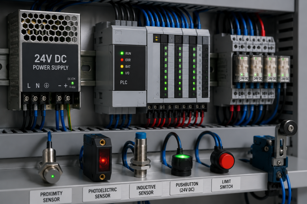
Open almost any modern industrial control panel and one voltage appears again and again: 24V DC.
The programmable logic controller uses it. Proximity sensors use it. Relay coils, indicator lights, solenoid valves, safety modules, communication devices and operator controls often use it too.
That consistency is not accidental.
Factories contain large motors, contactors, variable-frequency drives, heaters and other equipment operating at potentially dangerous voltages. Yet the control system watching and coordinating those machines needs a power level that technicians can work with more safely, devices can share easily and signals can transmit reliably through a rather unfriendly electrical environment.
Twenty-four volts DC became the practical middle ground.
It is not the lowest possible control voltage. It is not completely immune to interference, and it cannot power every industrial load. Still, it offers an unusually useful combination of safety, compatibility, reliable switching and worldwide component availability.
In short, it gets the job done without creating unnecessary drama.
Industrial Machines Use More Than One Voltage
A control cabinet rarely operates at only one voltage.
A typical machine may have:
- 400V three-phase AC supplying motors;
- 230V AC supplying heaters, sockets or auxiliary equipment;
- a DC bus inside a variable-frequency drive;
- 24V DC supplying the control system;
- 5V, 3.3V or lower voltages inside electronic devices.
The high-power circuits perform the physical work. They turn motors, heat materials, drive pumps and operate machinery.
The 24V DC circuit handles much of the decision-making and signalling.
For example, a photoelectric sensor may detect a box and send a 24V signal to a PLC input. The PLC program then decides whether to energise a 24V relay or solenoid output. That smaller control device may ultimately switch a contactor, valve or drive command controlling much greater power.
The 24V circuit is therefore not expected to run the entire machine.
It tells the machine what to do.
Why Not Use Mains Voltage for Every Control Signal?
Older industrial systems often used 110V, 120V or 230V AC control circuits. Some modern installations still do, particularly where legacy equipment, long cable runs or large contactor coils are involved.
Mains-voltage controls can work reliably, but they bring additional risk and design requirements.
A broken wire, exposed terminal or damaged push button may carry a hazardous voltage. Maintenance becomes more demanding, and compact electronic sensors generally cannot connect directly to such circuits.
With 24V DC, many control devices can operate at a much lower voltage. This reduces the likelihood of a dangerous electric shock under ordinary dry conditions and allows manufacturers to build smaller electronic components.
Lower voltage also makes it easier to connect PLCs, sensors and communication modules without placing mains voltage throughout every part of the machine.
That said, 24V DC should not be treated as harmless in every situation. High-current DC supplies can cause severe short-circuit heating, melted wiring and fires. Wet environments, damaged skin and unusual contact conditions also change electrical risk.
Lower risk does not mean zero risk.
Why 24 Volts Instead of 5 or 12 Volts?
If lower voltage is safer, why stop at 24 volts? Why not operate the entire control system at 5V?
Because factory wiring is not a tiny circuit board.
A 5V signal works wonderfully inside computers and electronic modules where conductors are short and carefully controlled. Run that same voltage through tens of metres of cable, connectors, terminal blocks and field devices, and voltage drop becomes much more troublesome.
Every cable has resistance. When current flows, part of the supply voltage is lost along the cable:
[
V_{drop}=IR
]
If a circuit loses 2 volts, the effect depends heavily on the original supply.
On a 5V system, losing 2 volts means only 3 volts reach the device. It may stop working completely.
On a 24V system, the same 2-volt loss leaves 22 volts. Many industrial devices will continue operating normally.
This larger voltage margin makes 24V DC far more suitable for field wiring than the low logic voltages used inside electronic circuits.
Why Not Use 48V DC?
A higher DC voltage could reduce current and voltage drop even further.
Indeed, 48V DC is used in telecommunications, network equipment, vehicle systems and certain industrial applications. However, it is less universally adopted for ordinary automation sensors and PLC inputs.
At 24V DC, manufacturers can provide a useful balance between:
- lower electrical risk;
- manageable current;
- good tolerance of cable voltage drop;
- compact device construction;
- broad component compatibility;
- practical switching performance.
Raising the voltage would improve some aspects while complicating others. Components would need different ratings, switching arcs could become more significant and the familiar 24V ecosystem would disappear.
Industrial standards often survive because nearly everyone already supports them.
Once thousands of sensors, relays, PLCs and power supplies are designed for the same voltage, changing that voltage becomes rather inconvenient.
24V DC Offers a Safer Control Voltage
One of the strongest reasons for using 24V DC is personnel safety.
When supplied through an appropriately designed isolated power supply, 24V control circuits may be arranged as SELV or PELV systems, depending on the grounding and protection method.
These terms refer to extra-low-voltage systems that are separated from hazardous mains voltages and designed to reduce shock risk.
The distinction matters:
- SELV circuits are separated from earth and higher voltages under specified conditions.
- PELV circuits also use protective separation but may have one side connected to protective earth.
Many industrial control systems use a grounded 0V reference, making them closer to a PELV-style arrangement.
Grounding the DC control supply can help fault detection and reduce unpredictable floating voltages. However, grounding must be planned carefully. Random earth connections scattered around the machine can create ground loops and signal problems.
There is a proper way to do it. There is also the way where someone adds a green-yellow wire because “it seemed helpful.”
Those are not always the same thing.
A Standard Voltage Makes Devices Compatible
Industrial automation relies on equipment from many manufacturers.
A single machine may contain:
- a Siemens, Allen-Bradley, Schneider Electric, Mitsubishi, Omron or Beckhoff PLC;
- sensors from SICK, IFM, Pepperl+Fuchs or Banner;
- relays from Phoenix Contact, Finder or Weidmüller;
- valves from Festo or SMC;
- safety components from Pilz or ABB;
- power supplies from another manufacturer entirely.
The widespread use of 24V DC allows these devices to work within the same control-power system.
A designer does not need a separate supply for every brand. Replacement parts are easier to source, spare components are easier to standardise and maintenance technicians already understand the expected voltage levels.
This compatibility is one reason 24V DC is so deeply established.
Standards are not exciting until something fails at 2 a.m. Then having a common replacement on the shelf becomes extremely exciting.
PLC Inputs Are Commonly Designed for 24V DC
A PLC input detects whether an external field signal is on or off.
The signal may come from:
- a push button;
- a limit switch;
- a pressure switch;
- a proximity sensor;
- a relay contact;
- a safety device;
- another controller.
A typical 24V digital input is designed to recognise a voltage range as logic ON and a lower range as logic OFF. The exact thresholds depend on the input module and relevant standards.
The input does not simply assume that anything above zero is ON. It usually includes filtering and threshold behaviour to reject small leakage currents and electrical noise.
Internally, the input may use:
- current-limiting resistors;
- optocouplers;
- filtering components;
- protection diodes;
- voltage comparators;
- isolation circuitry.
The field wiring therefore operates at 24V, while the PLC processor itself runs at a much lower internal voltage.
The input module forms the protective bridge between the messy factory floor and the delicate electronics inside the controller.
Why 24V Signals Tolerate Noise Better Than Low-Voltage Logic
Factories are electrically noisy places.
Motors switch on and off. Contactors open under load. Solenoid coils release stored magnetic energy. Variable-frequency drives rapidly switch high voltages. Long cables run beside power conductors, sometimes despite everyone agreeing that they shouldn’t.
These events can induce unwanted voltages into control wiring.
A 24V signal has more separation between its normal ON level and its OFF threshold than a 3.3V or 5V logic signal. A small induced disturbance that might confuse a low-voltage electronic input may remain far below the threshold of a properly designed 24V PLC input.
The higher signal level provides useful noise margin.
But 24V DC is not magically noise-proof.
Reliable control wiring still depends on:
- proper cable routing;
- separation between power and signal cables;
- shielded cable where required;
- correct shield termination;
- suppression across coils;
- suitable grounding;
- filtered PLC inputs;
- avoiding ground loops;
- correct cable types;
- sound cabinet layout.
A badly installed 24V circuit can still generate false signals.
Twenty-four volts gives the designer more breathing room. It does not excuse chaos.
DC Provides a Clear and Stable Signal State
A DC control signal has a fixed polarity and a relatively steady voltage.
That makes it well suited to electronic sensors and semiconductor outputs. A device can represent one condition by supplying current and another by removing it.
AC control signals repeatedly pass through zero as the waveform changes direction. Mechanical relays can tolerate that, but electronic input circuits require additional rectification and filtering.
DC simplifies many sensor and PLC interface designs.
It also supports polarity-sensitive devices, semiconductor protection and diagnostic functions. Modern automation equipment can detect overloads, short circuits, wire breaks and other conditions more easily when its power and signal system is based on a defined DC supply.
Sensors Commonly Use Three-Wire 24V Connections
Many industrial proximity, photoelectric and pressure sensors use three wires:
- brown for +24V;
- blue for 0V;
- black for the output signal.
The colour convention is common, though documentation should always be checked rather than trusted blindly.
The sensor receives continuous 24V power through the brown and blue wires. When it detects a target, the output changes state and sends a signal to the PLC.
This arrangement allows the sensor to contain active electronics such as:
- an oscillator;
- an optical emitter;
- an amplifier;
- signal processing;
- an output transistor;
- status LEDs;
- protection circuitry.
A simple mechanical switch does not require its own power. An electronic sensor does, and 24V DC provides a convenient standard supply.
PNP and NPN Sensor Outputs
Industrial DC sensors are commonly available with PNP or NPN transistor outputs.
A PNP sensor typically switches positive voltage to the PLC input. When active, it sources current from +24V through the output and into the input circuit.
An NPN sensor typically switches the signal toward 0V. When active, it sinks current from the input circuit.
Which style is used often depends on regional practice, machine standards and PLC input design.
PNP wiring is especially common in European industrial systems. One practical advantage is that a short from a signal conductor to grounded metal is more likely to produce an OFF condition or a detectable fault rather than unintentionally activating an input, depending on the exact circuit arrangement.
NPN systems remain common in many applications, particularly in some Asian equipment and legacy designs.
The important point is compatibility.
A PNP sensor must be connected to a suitable sinking PLC input. An NPN sensor requires a suitable sourcing input. A voltage match alone does not guarantee that the current direction is correct.
The sensor may say 24V on the label and still refuse to cooperate if the interface type is wrong.
Two-Wire Sensors Work Differently
Some industrial sensors use only two wires and are connected in series with the load, rather like an electronic switch.
Because the sensor needs power for its internal electronics, a small leakage current may continue flowing even when the output is considered off. It may also have a noticeable voltage drop when on.
This can create problems with sensitive PLC inputs or relay coils.
For example, leakage current may be enough to make an input indicator glow faintly or prevent the input voltage from falling fully to zero. A load resistor or interface module may be needed.
Again, 24V DC provides a common platform, but the actual behaviour depends on the sensor design.
Automation wiring has a charming way of looking simple right up until the last two volts refuse to disappear.
Why Relay Coils Often Use 24V DC
Relays and contactors allow a low-power control signal to switch another circuit.
A 24V DC relay coil fits naturally into a control system already using 24V sensors and PLC outputs. The same power supply can energise the coil, while the relay contacts switch another voltage or provide galvanic separation.
Interposing relays are often used when:
- the load current exceeds the PLC output rating;
- electrical isolation is required;
- several contacts are needed;
- a different voltage must be switched;
- field wiring needs convenient separation;
- maintenance requires a replaceable interface.
Using 24V DC coils also avoids distributing mains voltage through every PLC output and control terminal.
A failed relay coil is inconvenient.
A mains-voltage fault on a crowded output module is potentially rather more interesting.
DC Coils Need Suppression
A relay, contactor or solenoid coil stores energy in its magnetic field.
When the PLC output switches the coil off, the collapsing magnetic field tries to keep current flowing. This can create a high-voltage spike known as inductive kickback.
Without protection, that spike may damage the PLC output, create electromagnetic interference or cause arcing.
DC coils are commonly suppressed using:
- flyback diodes;
- diode and Zener combinations;
- transient-voltage suppressors;
- varistors;
- RC networks.
A basic flyback diode is effective and inexpensive, but it slows the collapse of coil current. That may slightly increase relay or valve release time.
Faster suppression methods allow the magnetic field to collapse more quickly but clamp at a higher voltage.
The correct choice depends on the required switching speed and output rating.
“Just put a diode on it” works often enough to become a habit, though not every machine appreciates the slower release.
Solenoid Valves Commonly Operate at 24V DC
Pneumatic and hydraulic systems use solenoid valves to control air or fluid flow.
A PLC output energises a coil, creating a magnetic field that moves the valve mechanism. Many industrial valves use 24V DC coils because they can connect directly to the standard control supply.
This simplifies wiring and spare-parts management.
However, solenoid coils can draw significantly more current than a typical sensor. Several valves switching at once may create a noticeable load on the power supply.
Some coils also draw a high initial current before settling. Others include power-saving electronics that reduce current after actuation.
The power supply and output module must be selected for the actual load, not merely the number of devices.
Ten small LEDs and ten solenoid valves are both “ten outputs.” Electrically, they are not remotely the same thing.
PLC Outputs May Be Transistor or Relay Type
A PLC can control field devices through different output technologies.
Transistor outputs
Transistor outputs switch DC loads electronically.
They are fast, silent and suitable for frequent operation. They are commonly used for:
- indicator lamps;
- small relays;
- solenoid valves;
- high-speed pulse signals;
- other 24V DC devices.
Their limitations include polarity requirements and maximum current ratings. They can also fail if inductive suppression is inadequate.
Relay outputs
Relay-output modules contain physical contacts.
They can often switch AC or DC and do not have the same sourcing or sinking polarity limitations. However, they are slower, produce mechanical noise and eventually wear out.
For rapidly switching applications, transistor outputs are usually preferred.
For occasional switching of different voltages, relay outputs can be convenient.
Both fit into 24V automation systems, but in different ways.
Why Dedicated Industrial Power Supplies Are Used
The 24V control voltage is usually produced by a dedicated DIN-rail power supply.
This unit converts the incoming AC supply into regulated DC. A modern industrial power supply commonly provides:
- galvanic isolation;
- regulated output voltage;
- short-circuit protection;
- overload protection;
- overvoltage protection;
- temperature protection;
- status indication;
- adjustable output voltage;
- high efficiency.
Industrial supplies are designed to operate in electrical cabinets where temperature, vibration and supply disturbances may be less friendly than in an office.
They may also support features such as:
- parallel operation;
- redundancy;
- current sharing;
- electronic circuit protection;
- DC-OK relay contacts;
- boost current for starting loads;
- communication and diagnostics.
A cheap consumer adapter may produce 24V on a multimeter.
That does not make it an ideal power source for a production line expected to run around the clock.
Why the Output Is Sometimes Adjusted Above 24 Volts
Many industrial 24V power supplies include an adjustment control.
Technicians sometimes set the output slightly above 24V—perhaps around 24.5V or another value permitted by the connected equipment—to compensate for cable and distribution losses.
This must be done carefully.
Raising the supply too far can overstress devices, increase coil heating and exceed input ratings. The correct approach is to calculate or measure voltage drop and confirm the allowed operating range of every connected component.
Using 27 volts to “make sure it reaches the end” is not an engineering method.
It is a future troubleshooting exercise.
Power-Supply Sizing Is More Than Adding Nameplate Currents
The control power supply must support all connected loads under the worst expected conditions.
These may include:
- PLC and remote I/O modules;
- sensors;
- relays;
- solenoid valves;
- safety devices;
- HMIs;
- network switches;
- communication equipment;
- indicators;
- braking or holding devices.
The continuous current is important, but so are startup and switching peaks.
A system may operate normally until several valves energise together, at which point the voltage collapses and the PLC resets. The fault then looks like a software problem because the machine stops mid-sequence.
In reality, the power supply simply ran out of breath.
Good design includes spare capacity and checks transient demand, cable voltage drop and environmental derating.
Why Separate 24V Supplies May Be Used
A large automation system may use more than one 24V DC supply.
Designers may separate:
- PLC and control electronics;
- sensors;
- solenoid valves;
- safety circuits;
- communication equipment;
- field I/O;
- high-noise loads.
This prevents one fault from shutting down the entire machine.
For example, a shorted valve cable could collapse a shared 24V bus and reset the PLC. With separate supplies or properly coordinated electronic protection, the affected branch can trip while the controller remains alive and reports the fault.
Separation also reduces noise coupling between sensitive electronics and inductive loads.
There is a balance, though. Too many unrelated supplies can create confusing references and grounding problems.
A clean distribution plan beats both extremes.
Electronic Circuit Breakers Improve 24V Distribution
Traditional fuses and miniature circuit breakers can protect 24V DC branches, but they do not always operate as expected with switch-mode power supplies.
A power supply may enter current limiting instead of delivering enough fault current to trip a conventional protective device quickly. The entire output voltage may then collapse.
Electronic circuit protectors solve this by monitoring individual branches and disconnecting the faulty circuit according to defined current limits and delay characteristics.
They may provide:
- selective branch shutdown;
- remote reset;
- diagnostic contacts;
- current monitoring;
- status LEDs;
- communication with the PLC.
This keeps healthy parts of the control system running when one field circuit develops a short.
It is much easier to diagnose “channel 6 tripped” than “the whole cabinet is dark.”
Noise Resistance Depends on Grounding and Cable Routing
The phrase “24V is noise resistant” is true only up to a point.
A strong disturbance can still create false inputs or damage equipment. Long parallel cable runs near motor leads are particularly troublesome because VFD output cables carry fast voltage transitions.
Good practice may include:
- separating control and power wiring;
- crossing noisy cables at right angles;
- using twisted pairs;
- using shielded cables for analogue and high-speed signals;
- grounding shields according to the system design;
- installing surge protection;
- suppressing contactor and solenoid coils;
- bonding machine metalwork correctly;
- avoiding oversized cable loops.
Digital 24V signals are generally more forgiving than millivolt sensor signals, but careless installation can defeat that advantage.
Electrical noise has no respect for a neatly written schematic.
Analogue Signals Often Share the Same 24V Supply
Industrial transmitters commonly use 24V DC power even when their actual measurement signal is analogue.
A well-known example is the 4–20mA current loop.
A pressure, temperature or flow transmitter may receive power from the 24V loop and regulate the current according to the measured value:
- 4mA represents the minimum reading;
- 20mA represents the maximum;
- a value below the normal range may indicate a fault.
Current loops are highly useful over long distances because the signal is based on current rather than the exact voltage at the receiver. Cable voltage drop has less effect as long as enough voltage remains for the transmitter and input resistance.
The 24V supply provides enough headroom for the transmitter, cable and receiving device in many common installations.
Not every loop can use exactly 24V under every condition, but it is the standard starting point.
Safety Systems Also Commonly Use 24V DC
Emergency-stop circuits, safety relays, light curtains, guard switches and safety PLCs commonly operate at 24V DC.
This allows safety devices to integrate with the machine’s control system while maintaining monitored, redundant circuit structures.
A safety system may check for:
- short circuits;
- crossed channels;
- contact welding;
- timing differences;
- wire breaks;
- external device feedback.
The use of 24V DC does not itself make a circuit safety-rated. Safety depends on the architecture, device certification, diagnostic coverage and required performance level or safety integrity level.
A normal PLC input supplied with 24V is not automatically a safety input.
The voltage is common. The responsibility is not.
Why 0V Is Not Always the Same as Earth
In a 24V DC system, the negative side of the supply is commonly labelled 0V, M or DC negative.
Protective earth is a separate conductor intended for electrical safety and bonding exposed conductive parts.
The 0V conductor may be connected to protective earth at one controlled point, but that does not make them interchangeable everywhere.
Using protective earth as a normal return conductor can create:
- unpredictable current paths;
- voltage differences;
- electromagnetic interference;
- diagnostic problems;
- unsafe fault conditions.
Control-current return should normally flow through the designated 0V wiring.
Protective earth has another job.
Giving both conductors similar-looking terminal bars does not mean they can swap careers.
Common Problems in 24V DC Systems
Although 24V automation systems are reliable, familiar faults still occur.
Voltage drop
Long cable runs, undersized conductors or high-current loads can reduce the voltage reaching field devices.
Symptoms may include intermittent sensors, chattering relays or valves that fail to actuate.
Loose 0V connection
A poor return connection may cause several unrelated signals to behave strangely. Inputs can flicker, analogue readings may drift and devices may reset.
The positive conductor often receives the blame, while the loose 0V quietly causes trouble for an entire group.
Short circuit
A damaged field cable can pull down the supply or trip branch protection.
Without selective protection, one short may stop the complete control system.
Reversed polarity
Many devices include reverse-polarity protection, but not all of them survive every wiring mistake.
Checking the brown and blue conductors before applying power remains a worthwhile tradition.
Ground loops
Multiple uncontrolled 0V-to-earth connections can allow unwanted circulating current and introduce noise into sensitive signals.
Inductive spikes
Unsuppressed relays, contactors and valves may damage transistor outputs or create random PLC input transitions.
Overloaded supply
A power supply may work during testing and fail only when all outputs are active during production.
The machine passed commissioning because nobody made it perform its actual job all at once. It happens.
Is 24V DC Always the Best Choice?
No voltage is perfect for every application.
Other control voltages may be chosen when:
- legacy equipment uses AC controls;
- very long cable runs require another approach;
- large contactor coils need more power;
- telecommunications equipment uses 48V DC;
- intrinsically safe systems impose special limitations;
- mobile machinery uses 12V or 48V batteries;
- specialised devices require another supply;
- power-over-Ethernet or fieldbus systems provide power differently.
Some sensors and actuators also use broad supply ranges, such as 10–30V DC, rather than exactly 24.0V.
Twenty-four volts is a nominal system voltage. Real devices are normally designed to tolerate a specified operating range around it.
The datasheet remains the final judge.
Why 24V DC Became the Industrial Default
Twenty-four volts DC succeeds because it balances several competing needs remarkably well.
It is low enough to reduce shock risk compared with mains-voltage controls. It is high enough to tolerate realistic cable voltage drops and induced electrical noise. It powers active sensors, PLC inputs, relays and valve coils without requiring a separate voltage for every device.
It is also supported almost everywhere.
Manufacturers build around it. Electricians recognise it. Spare parts are widely available, and complete control systems can be assembled from equipment produced by different companies.
That shared standard saves time from design through maintenance.
A factory still needs careful grounding, proper protection, sensible cable routing and correctly sized power supplies. Twenty-four volts cannot rescue a poor installation from every mistake.
But as a common language for industrial controls, it is difficult to beat.
The motors may run on hundreds of volts and enormous currents.
Most of the conversation telling them when to start and stop happens quietly at 24V DC.