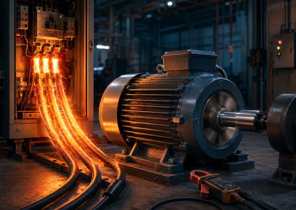
The motor runs happily at 12 A once the machine reaches normal speed.
Press the start button, though, and the current briefly jumps to 60 A, 80 A or perhaps even more. The workshop lights dip. A contactor gives a solid clunk. Somewhere nearby, a control transformer sounds slightly offended.
Then, after a second or two, everything settles down.
So, why does a motor draw high current at startup?
At the moment of starting, the motor shaft is stationary. It has not yet developed the electrical effects that normally oppose the incoming supply and limit current. In a three-phase induction motor, the stationary rotor also behaves somewhat like the short-circuited secondary winding of a transformer.
The motor therefore draws a large locked-rotor current.
As the motor accelerates, its internal electrical conditions change. The effective opposition to current increases, rotor slip decreases and the current falls toward its normal operating value.
A brief current surge is expected.
A motor that continues drawing startup current, however, is usually stalled, overloaded, incorrectly connected or unable to accelerate.
Normal Running Current Versus Starting Current
A motor’s nameplate current normally describes the approximate current it draws while operating at its rated voltage, frequency, load and connection.
For example:
Rated motor current: 12 AThat does not mean the motor will stay below 12 A during starting.
A direct-on-line induction motor may briefly draw several times its rated current. Depending on the motor design and supply conditions, the starting current may commonly fall somewhere around five to eight times the full-load current, although some motors are outside that range.
A 12 A motor might therefore draw:
Starting current: approximately 60–96 AThe exact value depends on:
- Motor construction
- Rated power
- Rotor design
- Supply voltage
- Supply impedance
- Cable length
- Winding connection
- Mechanical load
- Starting method
The current is high, but under normal conditions it lasts only while the motor accelerates.
The electrical installation must be designed to tolerate this temporary surge without allowing the cable, starter or protective equipment to overheat.
What Is Back EMF?
When electrical current flows through a motor winding, it creates a magnetic field.
As the motor begins rotating, electromagnetic effects inside the machine produce a voltage that opposes the applied supply. This opposing voltage is commonly called back electromotive force, or back EMF.
The word “back” does not mean the voltage travels physically backwards through the cable. It means the internally generated voltage opposes the voltage driving current into the winding.
A simplified relationship is:
Motor current depends on:

Applied voltage
minus
Opposing internal voltage
When the motor is stationary, this opposing rotational effect is absent or much smaller.
The motor therefore has less internal opposition to the supply, and a large current flows.
As speed increases, the opposing effect becomes stronger and the current falls.
This explanation is especially intuitive for DC and permanent-magnet motors. In a three-phase induction motor, the detailed behaviour is described through magnetic induction, rotor slip and the motor’s equivalent impedance—but the practical result is similar:
At zero speed, current is high. At normal speed, current is much lower.
An Induction Motor Is Similar to a Transformer
A stationary induction motor behaves somewhat like a transformer.
The stator windings act like the transformer’s primary winding. The rotor acts like a secondary winding whose conductors are effectively short-circuited.
At the moment power is applied:
- The stator creates a rotating magnetic field.
- The stationary rotor experiences maximum relative movement against that field.
- A strong voltage is induced in the rotor conductors.
- Large rotor current flows.
- The stator draws additional current from the supply.
This produces strong starting torque—but also high starting current.
The rotor is not physically connected to the electrical supply in an ordinary squirrel-cage motor. Its current is induced magnetically.
At standstill, the difference between the rotating magnetic field speed and the rotor speed is at its maximum.
That difference is called slip.
What Is Motor Slip?
The magnetic field inside the stator rotates at synchronous speed.
Synchronous speed depends on the supply frequency and number of motor poles:
Synchronous speed = (120 × frequency) ÷ number of polesFor a four-pole motor on 50 Hz:
Synchronous speed = (120 × 50) ÷ 4

Synchronous speed = 1,500 rpm
At the instant of startup:
Magnetic-field speed: 1,500 rpm
Rotor speed: 0 rpm
The rotor is therefore experiencing maximum slip.
Slip can be expressed as:
Slip = (Synchronous speed − Rotor speed) ÷ Synchronous speedAt standstill:
Slip = (1,500 − 0) ÷ 1,500

Slip = 1, or 100%
As the rotor accelerates, its speed moves closer to the rotating-field speed.
Suppose the motor reaches 1,450 rpm:
Slip = (1,500 − 1,450) ÷ 1,500

Slip ≈ 3.3%
At this point, the relative speed between the rotor and magnetic field is much lower. Rotor-induced current falls, and the stator current settles toward the level required by the mechanical load.
The motor never quite reaches synchronous speed during normal motoring operation. It needs some slip to induce rotor current and produce torque.
What Is Locked-Rotor Current?
Locked-rotor current is the current drawn when rated voltage and frequency are applied while the rotor is prevented from turning.
At the instant of a direct-on-line start, the motor is effectively in this condition because its speed is zero.
The rotor is not mechanically locked during a healthy start, of course. It begins accelerating almost immediately.
But electrically, the first moment looks much the same.
Locked-rotor current is sometimes called:
- Starting current
- Inrush current
- Startup current
- LRA, or locked-rotor amperes
The terms are closely related, although manufacturers may define and measure them under specific test conditions.
The locked-rotor value may appear on the motor documentation or as a code used to estimate the motor’s starting apparent power.
Why the Motor’s Winding Resistance Does Not Limit Current Enough
Motor windings are made from copper and have relatively low resistance.
Low resistance is desirable because it reduces heating and improves efficiency during normal operation.
But if current were limited only by the winding’s DC resistance, the startup current would be enormous.
During normal running, the motor’s inductive and electromechanical behaviour provides additional opposition to current.
At standstill, that effective impedance is lower than during normal operation.
This is why simply measuring the winding resistance with a multimeter and applying Ohm’s law does not predict the normal AC running current correctly.
A motor winding may measure only a few ohms—or less—yet operate normally without creating a direct short circuit.
Its AC behaviour is not determined by resistance alone.
How the Current Changes During Acceleration
The current does not always fall smoothly in a perfect straight line.
A typical starting sequence looks roughly like this:
Power applied
↓
Current jumps to locked-rotor value
↓
Motor begins producing torque
↓
Rotor accelerates
↓
Slip decreases
↓
Effective motor impedance changes
↓
Current falls toward normal running value
The speed of this process depends heavily on the connected load.
An unloaded motor may reach normal speed quickly.
A motor driving a heavy conveyor, large fan, crusher or high-inertia flywheel may remain in the high-current region much longer.
That extra time matters.
Heating energy increases with both current and duration.
A high current lasting half a second may be acceptable. The same current lasting twenty seconds can overheat the windings, damage the contactor or operate the motor protection.
Why Motor Acceleration Matters
A motor accelerates when its developed torque is greater than the resisting torque of the load.
The difference between those torques provides acceleration.
In simplified terms:
Motor torque > Load torque
→ Motor accelerates
If the available motor torque only barely exceeds the load torque, acceleration will be slow.
The motor then draws elevated current for longer.
If the load torque is greater than the available starting torque:
Motor torque < Load torque
→ Motor does not accelerate
The motor remains stalled and continues drawing locked-rotor current.
Possible causes include:
- Jammed machinery
- Seized bearings
- Excessive mechanical load
- Incorrect motor connection
- Low supply voltage
- Missing phase
- Incorrect starter selection
- Excessive voltage drop
- A pump starting against unsuitable conditions
- A compressor starting with pressure still present
A motor that cannot accelerate is not merely running slowly.
It may be heating very rapidly.
Why Low Voltage Can Make Starting Worse
At first glance, reducing voltage appears useful because it lowers starting current.
That is true—but motor starting torque also falls sharply with voltage.
For an induction motor, torque is approximately proportional to the square of applied voltage under comparable conditions.
For example, if voltage falls to 90%:
Approximate torque = 0.9²

Approximate torque = 0.81
The motor may have only about 81% of its expected torque.
If voltage falls to 80%:
Approximate torque = 0.8²

Approximate torque = 0.64
Now the motor may produce only about 64% of the original torque.
This can create an awkward chain of events:
Voltage drops
↓
Starting torque decreases
↓
Motor accelerates more slowly
↓
High current continues longer
↓
Voltage remains depressed
↓
Motor may stall or overheat
Lower voltage reduces the instantaneous current, but it can make the overall start worse when the motor no longer has enough torque to accelerate the load.
Why Starting Current Causes Voltage Dips
Every power supply, transformer and cable has impedance.
When a motor draws a large starting current, voltage drops across that impedance.
The result is a temporary reduction in voltage at the motor and elsewhere on the same network.
Common symptoms include:
- Lights dimming
- Contactors dropping out
- PLCs restarting
- Control relays chattering
- Computers rebooting
- Other motors slowing briefly
- Undervoltage alarms
- VFDs reporting DC-bus undervoltage
A small, brief dip may be acceptable.
A deep or prolonged dip suggests that:
- The motor is too large for the available supply
- The transformer is undersized
- Supply cables are too long or too small
- The motor takes too long to accelerate
- Several motors start simultaneously
- The starting method is unsuitable
- There is a weak utility connection
- A loose connection is adding impedance
The motor and supply must be considered together.
A perfectly healthy motor can still cause trouble when connected to a supply that is not strong enough for direct-on-line starting.
Why Lights Dim When a Motor Starts
Household refrigerators, air conditioners, pumps and workshop compressors can all produce brief voltage dips.
When the motor starts, its high current creates voltage drop in the supply wiring.
The lighting circuit temporarily receives less voltage, so the lamps dim.
A slight, momentary dip may be normal with a substantial motor load.
More concerning signs include:
- Severe dimming
- Lights remaining dim while the motor runs
- Repeated failed starts
- Buzzing from the motor
- Breakers tripping
- A hot plug or socket
- The motor taking several seconds longer than usual
- Lights brightening and dimming unpredictably
These symptoms may indicate a failing motor, weak supply, damaged start capacitor, loose connection or overloaded circuit.
Why Breakers Do Not Trip on Every Motor Start
A motor’s normal starting current may be many times its running current.
If an ordinary protective device reacted instantly to every short surge, healthy motors would trip the circuit whenever they started.
Motor circuits therefore use protection selected to tolerate normal acceleration while still disconnecting sustained overloads and short circuits.
Depending on the installation, protection may include:
- Motor-protection circuit breakers
- Thermal overload relays
- Electronic overload relays
- Fuses
- Short-circuit protective devices
- Temperature sensors
- Locked-rotor protection
- Stall protection
- Start-time supervision
The protective curve matters.
A brief surge is allowed.
A motor that stays near locked-rotor current for too long must be disconnected.
Selecting a larger breaker simply to stop nuisance tripping can leave the motor and cable dangerously underprotected.
The correct solution is coordinated motor-circuit design—not a breaker with a more relaxed attitude.
Direct-on-Line Starting
A direct-on-line starter connects the motor directly to the full supply voltage.
It is commonly abbreviated as:
DOLAdvantages include:
- Simple circuit
- Low cost
- High starting torque
- Fast acceleration
- Easy troubleshooting
- Full motor capability during startup
Disadvantages include:
- High starting current
- Supply-voltage dips
- Mechanical shock
- Sudden acceleration
- Stress on belts, couplings and gearboxes
DOL starting is suitable when the supply can tolerate the inrush and the machine can tolerate the sudden torque.
It may be a poor choice for a large motor connected to a weak supply or driving delicate machinery.
What Is a Star-Delta Starter?
A star-delta starter reduces the voltage applied to each motor winding during startup.
It is intended for a motor designed to run in delta at the available line voltage and equipped with six accessible winding terminals.
During starting, the windings are connected in star:
Startup:
Motor windings connected in star
After the motor accelerates, the starter changes them to delta:
Normal running:
Motor windings connected in delta
In star, each winding receives approximately:
Line voltage ÷ √3or about 58% of the voltage it receives in delta.
For a 400 V supply:
400 V ÷ 1.732 ≈ 231 V per windingThe reduced winding voltage lowers the starting current.
Compared with direct delta starting, the line starting current is theoretically reduced to roughly one-third.
Starting torque is also reduced to roughly one-third.
That last point is crucial.
Star-delta is suitable only when the load can accelerate with the lower available torque.
Why Star-Delta Does Not Work for Every Load
A lightly loaded fan, pump or machine may accelerate successfully in star.
A loaded conveyor, compressor or high-breakaway-torque machine may not.
If the motor cannot accelerate sufficiently during the star period:
- Current remains elevated
- The motor heats up
- The transition to delta becomes severe
- The supply experiences another current surge
- The motor may stall
- Protection may trip
The timing must also be correct.
Switch to delta too early and the motor may produce a large transition current.
Wait too long and the motor may remain unnecessarily in a low-torque state.
A star-delta starter also requires proper interlocking between its contactors. Incorrect overlap between star and delta contactors can create a short circuit.
It is not simply three contactors and a timer thrown hopefully into a panel.
Open-Transition Star-Delta Starting
Many star-delta starters use an open transition.
The sequence is:
- Main and star contactors energize.
- The motor accelerates in star.
- The star contactor opens.
- A brief pause occurs.
- The delta contactor closes.
During the pause, the motor is momentarily disconnected.
Residual motor voltage may not be aligned with the incoming supply when delta reconnects. This can create a noticeable current and torque transient.
The transition may produce:
- A mechanical jerk
- A brief current spike
- Contactor stress
- Voltage disturbance
Closed-transition systems use additional components to reduce this interruption, but they are more complex and expensive.
What Is a Soft Starter?
A soft starter uses power-electronic devices—commonly thyristors—to control the voltage applied to the motor during startup.
Instead of applying full voltage instantly, it increases the voltage progressively.
This can reduce:
- Starting current
- Sudden torque
- Mechanical shock
- Belt stress
- Pipe pressure surges
- Voltage dips
A soft starter may allow adjustment of:
- Starting voltage
- Current limit
- Acceleration time
- Deceleration time
- Kick-start function
- Motor-protection settings
Once the motor reaches normal speed, many soft starters use a bypass contactor so current no longer passes continuously through the thyristors.
The motor then runs directly from the supply.
Soft Starters Reduce Torque Too
A soft starter reduces current by reducing motor voltage.
That also reduces available torque.
If the current limit is set too low, the motor may not accelerate.
The result can be:
- A long start
- Excessive motor heating
- Soft-starter overheating
- A stall alarm
- Failure to reach bypass
- Repeated trips
The correct settings depend on the load.
A centrifugal pump may respond very well to a soft starter.
A heavily loaded crusher or positive-displacement compressor may need greater starting torque than a heavily current-limited soft starter can provide.
Soft does not mean weak.
But it does mean the settings need to match the machine.
What Is a Variable-Frequency Drive?
A variable-frequency drive, or VFD, controls both the frequency and voltage supplied to the motor.
A typical VFD:
- Rectifies incoming AC into DC.
- Stores energy on a DC bus.
- Uses electronic switching to create a controlled three-phase output.
- Increases motor frequency and voltage gradually during acceleration.
At startup, the drive can begin at a low frequency rather than applying full 50 or 60 Hz immediately.
Because the rotating magnetic field starts slowly, the rotor can follow it without experiencing the same full locked-rotor condition as direct-on-line starting.
A properly selected and configured VFD can provide:
- Controlled starting current
- High starting torque
- Adjustable acceleration
- Speed control
- Controlled stopping
- Motor protection
- Process control
- Reduced mechanical stress
For difficult starts, a VFD is often the most capable option.
It is also the most complex of the common starting methods.
Why a VFD Can Produce Torque Without Huge Inrush
A direct-on-line starter immediately creates a magnetic field rotating at the full synchronous speed.
For a four-pole 50 Hz motor:
Field speed immediately becomes 1,500 rpmThe rotor is still at zero.
Slip is therefore 100%.
A VFD can begin with a much lower frequency.
For example, it may initially create a field rotating at only a small fraction of full speed. The rotor accelerates with it as frequency rises.
The drive also controls the voltage-to-frequency relationship to maintain suitable magnetic flux.
This allows the motor to produce useful torque while avoiding the enormous uncontrolled current associated with applying full frequency and voltage at standstill.
Soft Starter Versus VFD
Both devices can reduce starting stress, but they do different jobs.
Soft starter
- Controls voltage during starting and stopping
- Motor normally runs at fixed mains frequency
- Usually bypassed after acceleration
- Lower cost and simpler than a VFD
- Useful when speed control is unnecessary
VFD
- Controls both voltage and frequency
- Provides full speed control
- Can deliver strong low-speed torque
- Supports controlled acceleration and deceleration
- More expensive and complex
- Introduces harmonic, EMC and motor-insulation considerations
Choose based on the application rather than assuming one is universally better.
A pump needing gentle startup at fixed speed may suit a soft starter.
A conveyor requiring adjustable speed and controlled torque probably suits a VFD.
Why A Motor May Suddenly Start Drawing More Current Than Before
A motor that has always started normally but now takes longer or draws more current may have developed a problem.
Possible causes include:
- Increased mechanical load
- Worn or seized bearings
- Product buildup
- Misalignment
- Damaged gearbox
- Low supply voltage
- Loose terminals
- Failed phase
- Incorrect winding connection
- Rotor damage
- Motor winding fault
- Failing driven equipment
- Incorrect soft-starter settings
- VFD current-limit or tuning issues
Compare:
- Starting current
- Acceleration time
- Supply voltage during starting
- Current on all three phases
- Motor temperature
- Mechanical condition
- Historical readings
A motor does not usually decide to become lazy without a reason.
Something has changed.
What Happens During Phase Loss?
If one phase is missing before startup, a three-phase motor may fail to start and draw high current in the remaining phases.
It may hum, vibrate or rotate only if helped mechanically by the load conditions—none of which is acceptable.
If phase loss occurs while the motor is already running, it may continue turning while the remaining phases become heavily overloaded.
Possible causes include:
- Blown fuse
- Failed contactor pole
- Loose terminal
- Broken conductor
- Damaged switchgear
Phase-loss and current-unbalance protection can disconnect the motor before serious overheating occurs.
A motor humming at standstill is not thinking about starting.
It is converting a worrying amount of electricity into heat.
Why Repeated Starts Are Dangerous
Even when every individual start is successful, too many starts in a short period can overheat the motor.
Starting losses heat:
- Stator windings
- Rotor bars
- End rings
- Contactors
- Cables
- Starting equipment
The motor may not have enough time to cool between starts.
Manufacturers often specify:
- Maximum starts per hour
- Minimum time between starts
- Permitted cold starts
- Permitted hot starts
- Maximum acceleration time
Large motors and high-inertia loads can be particularly restricted.
A motor may handle one long acceleration from cold but not several repeated attempts after a failed start.
Pressing the start button again is not a cooling method.
High-Inertia Loads
Some machines resist changes in speed because they contain substantial rotating mass.
Examples include:
- Large fans
- Centrifuges
- Flywheels
- Crushers
- Long conveyors
- Large drums
- Heavy saws
- Industrial mixers
These loads may not require enormous breakaway torque, but they require torque for a long time while accelerating.
The motor remains above normal current until the stored rotational energy has been built up.
Starting-system selection must consider not only the peak current but also:
- Acceleration time
- Thermal motor capacity
- Load torque curve
- Number of starts
- Supply strength
- Mechanical stress
A current-limited start that looks gentle may take so long that it overheats the motor.
Slower is not automatically kinder.
Pump and Fan Starting Behaviour
Centrifugal pumps and fans often have load torque that rises with speed.
At low speed, the required load torque can be relatively modest. This makes them good candidates for soft starters and VFDs.
A VFD can accelerate the motor smoothly while avoiding unnecessary current and hydraulic shock.
Additional benefits may include:
- Reduced water hammer
- Controlled pressure
- Lower belt stress
- Reduced duct pressure surge
- Energy savings at reduced speed
However, not every pump is centrifugal.
Positive-displacement pumps and loaded compressors can require substantial torque from very low speed. Their starting method must be selected accordingly.
“Pump” is a category, not a torque curve.
Why Motor Cable Size Still Matters
A long or undersized cable adds resistance and reactance between the supply and motor.
During starting current, this creates a larger voltage drop.
The motor receives less voltage and produces less torque.
It then accelerates more slowly, which keeps the high current present for longer.
Possible symptoms include:
- Slow acceleration
- Failed starts
- Contactor dropout
- Motor-protection trips
- Cable heating
- Low terminal voltage
- Lights dimming severely
Cable selection must consider:
- Full-load current
- Starting current
- Installation method
- Cable length
- Ambient temperature
- Voltage-drop limits
- Protective-device coordination
A cable can be adequate for the running current yet still cause unacceptable voltage drop during starting.
Can a Start Capacitor Reduce Startup Current?
Single-phase motors often use capacitors to create phase shift and improve starting torque.
A start capacitor does not simply reduce current in the same way as a soft starter.
It helps create a rotating magnetic field and allows the motor to develop enough torque to accelerate.
If the start capacitor fails, the motor may:
- Hum
- Draw high current
- Fail to start
- Start only when unloaded
- Trip its protection
- Overheat
The motor remains near locked-rotor condition because it cannot accelerate properly.
Replacing the capacitor requires the correct capacitance, voltage rating and duty type.
A larger capacitor is not automatically an improved capacitor.
Warning Signs of a Motor Starting Problem
Investigate when you notice:
- Starting time becoming longer
- The motor humming without rotating
- Repeated breaker or overload trips
- Severe voltage dips
- Contactor chattering
- Unequal phase currents
- Burning smell
- Excessive motor temperature
- Mechanical vibration
- Starter thermal trips
- Soft starter failing to reach bypass
- VFD overcurrent or stall faults
- Motor starting only after several attempts
Disconnect and isolate the equipment before inspecting mechanical parts or terminals.
A stalled motor can start unexpectedly if the obstruction moves or the control circuit resets.
Common Motor-Starting Myths
“The motor draws high current because it needs extra power to begin moving”
That is only part of the story.
The main electrical reason is that the motor has low effective impedance at standstill and has not yet developed the opposing effects present at normal speed.
“Starting current means the motor is short-circuited”
Not exactly.
A stationary induction motor behaves somewhat like a transformer with a short-circuited secondary, but it is a designed operating condition that should last only briefly.
“A larger breaker fixes motor-starting trips”
Not necessarily.
The protection must be coordinated with the cable, contactor, overload relay and motor characteristics. Oversizing can create a fire or equipment-damage risk.
“Lower voltage always makes starting easier”
No.
It lowers current but also greatly reduces torque. The motor may accelerate more slowly or fail to start.
“Star-delta gives full starting torque with lower current”
No.
It reduces both current and torque. Starting torque is theoretically about one-third of direct delta starting torque.
“A soft starter controls motor speed during normal operation”
Usually not.
It mainly controls voltage during starting and stopping. A VFD is used when continuous speed control is required.
“A VFD eliminates all starting current”
No.
The motor still requires current to magnetize itself and produce torque. The VFD controls and limits that current rather than allowing uncontrolled direct-on-line inrush.
“If the motor eventually starts, everything is fine”
Not always.
An excessively long start can overheat the motor and damage the starting equipment even when the shaft eventually reaches full speed.
Choosing a Starting Method
The correct method depends on:
- Motor power
- Supply capacity
- Starting-current limits
- Required starting torque
- Load inertia
- Mechanical stress
- Desired acceleration time
- Need for speed control
- Number of starts per hour
- Process requirements
- Budget
Direct-on-line starter
Best when the supply is strong, the motor is reasonably small and sudden acceleration is acceptable.
Star-delta starter
Useful for suitable six-terminal motors driving loads that can accelerate with reduced torque.
Soft starter
Useful when smoother acceleration and reduced voltage dips are needed but normal running speed remains fixed.
Variable-frequency drive
Best when controlled acceleration, high starting torque, speed adjustment or advanced motor control is required.
There is no single best starter.
There is only the starter that suits the motor, supply and machine.
The Practical Answer
So, why does a motor draw high current at startup?
Because the motor is stationary.
At zero speed, it has not yet developed the internal opposing effects that help limit current during normal running. In a three-phase induction motor, slip is 100%, rotor-induced current is high and the motor behaves somewhat like a transformer with a short-circuited secondary.
This creates locked-rotor current, which may be several times the rated running current.
As the motor accelerates:
- Rotor slip decreases.
- The effective motor impedance changes.
- Opposing voltage effects increase.
- Current falls toward the normal operating value.
The starting surge can cause voltage dips, dim lights and stress on cables, contactors and transformers.
Several starting methods can reduce the disturbance:
- Star-delta starters reduce winding voltage, current and starting torque.
- Soft starters increase voltage gradually and limit current.
- VFDs control both frequency and voltage, allowing smooth acceleration with controlled torque.
A brief current surge is normal.
Current that remains high is not.
If the motor cannot accelerate because of low voltage, excessive load, a mechanical jam or a missing phase, it may remain near locked-rotor current and overheat rapidly.
The motor needs time to get moving.
Just not too much time.