A PLC program can compile without errors, download successfully and display perfectly reasonable values on the HMI—yet the machine still behaves unpredictably.
A valve opens too late. A counter misses products. Two sequences start at the same time. An alarm appears for only one scan and disappears before anyone notices it.
In many cases, the individual instructions are correct. The real problem is timing.
Industrial control systems do not evaluate every input and output continuously. PLCs execute their programs repeatedly in a cycle. Understanding that cycle is essential when troubleshooting logic that appears correct offline but fails on a running machine.
The PLC Scan Cycle
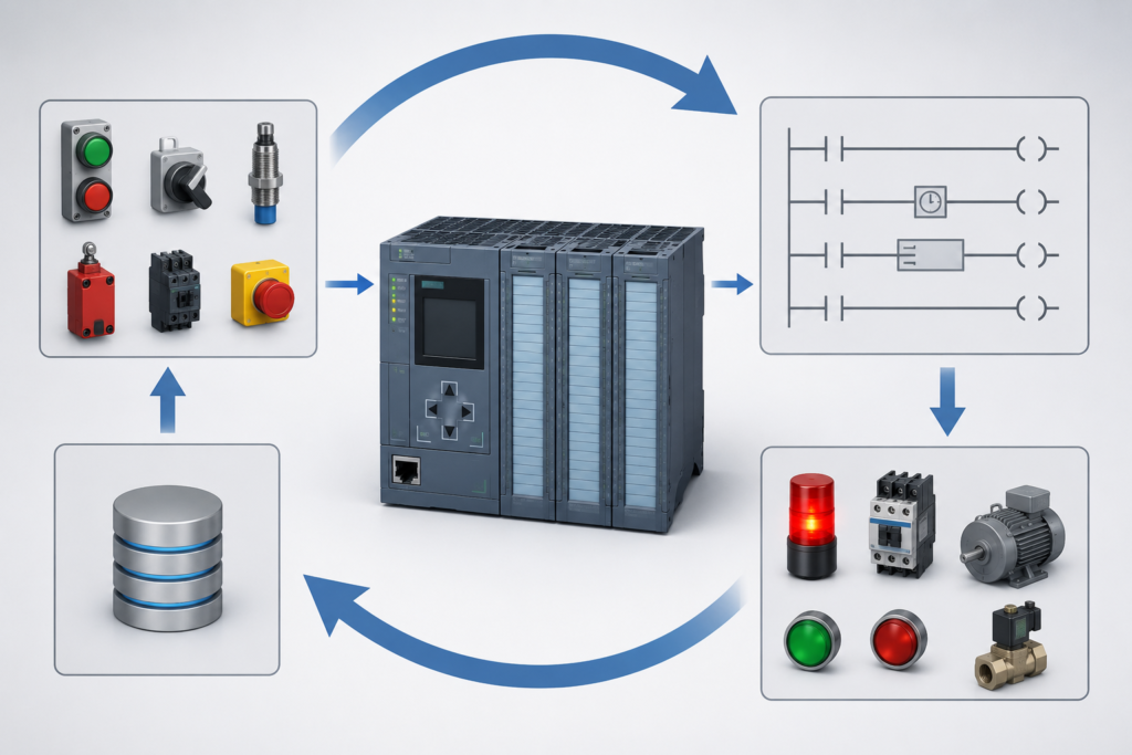
A simplified PLC scan normally includes four stages:
- Read physical inputs
- Execute the user program
- Update physical outputs
- Perform communication and system tasks
The controller then begins the next scan.
Depending on the CPU and program size, one cycle may take a fraction of a millisecond or several dozen milliseconds.
That sounds fast, but industrial events can be faster. A sensor pulse may begin and end between two input updates. A communication value may arrive after the program already used its previous value. Two logic networks may also modify the same tag during one scan.
The PLC does exactly what it was programmed to do—just not always when the programmer expected it to happen.
Inputs Are Usually Snapshots
At the beginning of a scan, the PLC copies the states of its physical inputs into an internal process image.
The program then works with that snapshot.
If a proximity sensor changes halfway through the scan, the logic may not see the new state until the next cycle. This can create confusion during commissioning because the physical signal has already changed, while the program still uses the earlier value.
Direct peripheral access is possible on some PLCs, but normal logic usually works with the process image because it provides a consistent input state throughout the scan.
Outputs Do Not Always Change Immediately
A standard output instruction normally changes a value in the output process image.
The physical output is updated later, after the program finishes executing.
For example, a network may set a motor command near the beginning of the program, while another network resets the same command later in the scan. The physical output may never switch on because only the final state is transferred to the output module.
This is why writing to one output from several locations is dangerous. The last executed instruction often wins.
A better approach is to calculate all operating conditions using internal tags and assign the physical output in one clearly defined location.
One-Scan Signals Can Be Missed
Positive and negative edge instructions create signals that normally remain active for only one program cycle.
They are useful for:
- Counting events
- Starting sequences
- Capturing button presses
- Triggering calculations
- Recording alarms
However, another task, communication block or HMI may not execute during that exact scan.
An HMI updating every 250 milliseconds will probably never display a signal that exists for only 5 milliseconds. The operator may therefore believe the bit never became true.
Important events should be latched until another part of the program acknowledges or resets them.
Remote I/O Adds Latency
Signals from remote PROFINET, PROFIBUS or other networked I/O are not necessarily updated at the same moment as local CPU inputs.
The total delay may include:
- Sensor response time
- Input-module filtering
- Network update time
- PLC scan time
- Program execution order
- Output-module update time
- Actuator response time
A sensor changing in the field may therefore take several cycles before its effect reaches the machine output.
The system may still be operating correctly, but the accumulated delay becomes important in high-speed counting, motion control, registration and safety-related applications.
Standard cyclic logic is not always suitable for fast events. Hardware interrupts, high-speed counters, technology modules or motion-control functions may be required.
Stale Tags Can Look Valid
Communication data often retains its last received value when communication is interrupted.
A pressure value of 4.2 bar may continue appearing on the HMI even though the remote device stopped communicating several minutes earlier.
The number looks believable, but it is no longer current.
Critical values should therefore include more than the process measurement. The program should also monitor:
- Communication status
- Data-valid bits
- Device diagnostics
- Update counters
- Timestamps
- Watchdog signals
A value without a quality status should not automatically be trusted.
Asynchronous Updates Create Mixed Data
Not every PLC task, network and device runs at the same rate.
A remote device may update one group of values every 20 milliseconds. The PLC may scan every 8 milliseconds. The HMI may refresh every 500 milliseconds.
The program can occasionally read a mixture of old and new data if related values are transferred separately.
For example, a drive may provide:
- Speed
- Current
- Status word
- Fault code
If these values do not arrive as one consistent data record, the PLC may briefly combine a new status word with an old fault code.
Where consistency matters, copy related communication data into a local structure only after a complete and valid update has been confirmed.
Race Conditions in PLC Programs
A race condition occurs when the result depends on which event or instruction happens first.
Consider a conveyor sequence where one condition starts the motor while another condition stops it. If both become true in the same scan, the result may depend entirely on program order.
The logic may appear correct when each condition is tested separately, but fail when both occur together.
Race conditions are especially common when:
- Multiple networks write to the same bit
- Automatic and manual commands overlap
- Several tasks share the same data
- Alarms reset themselves
- Communication and cyclic logic modify the same variable
- Sequence steps are changed from more than one location
Clear priority rules prevent many of these problems. Stop conditions, safety conditions and fault conditions should generally override start commands.
Why Simulation Can Be Misleading
Offline simulation is valuable, but it cannot perfectly reproduce a real industrial environment.
A simulation may not include:
- Network jitter
- Electrical noise
- Sensor bounce
- Mechanical movement
- VFD acceleration time
- Solenoid response delay
- Remote I/O latency
- Communication interruptions
- Operator timing
- Several faults occurring together
In simulation, the programmer changes one signal at a time and observes the expected result. In production, dozens of inputs may change within a few milliseconds.
Successful simulation proves that the logic works under the simulated conditions. It does not prove that every real timing combination has been tested.
Troubleshooting Scan-Dependent Problems
When logic behaves unpredictably, record the sequence rather than staring at the final values.
Useful diagnostic tools include:
- Trace functions
- Watch tables
- Sequence counters
- Event timestamps
- Diagnostic buffers
- Scan-time monitoring
- Communication-status words
- Temporary event latches
Instead of monitoring only whether a motor command is currently active, record why it started, why it stopped and which condition changed first.
Also check whether the same tag is written from several locations. Cross-reference tools in TIA Portal can reveal duplicate assignments that are easily missed during visual inspection.
Final Thoughts
Industrial logic can be structurally correct and still fail because the real process does not operate as a static diagram.
Inputs arrive at different times. Networks update asynchronously. Outputs are transferred after program execution. Communication values can become stale. One-scan events may disappear before another system reads them.
Good PLC programming therefore requires more than correct Boolean logic. It requires an understanding of scan time, execution order, data validity and the physical response of the machine.
When a program works in simulation but fails in production, the first question should not always be:
“Which instruction is wrong?”
A better question is:
“What happened first, and during which scan?”