The motor runs correctly. Its speed changes smoothly, the current looks normal and the VFD reports no fault.
Yet the nearby pressure transmitter suddenly becomes unstable.
An encoder occasionally loses position. A PLC input flickers when the motor accelerates. The machine’s communication network works perfectly while the drive is stopped, then begins reporting errors as soon as the VFD starts switching.
The motor cable may be radiating electrical noise.
So, why use shielded cable for a VFD?
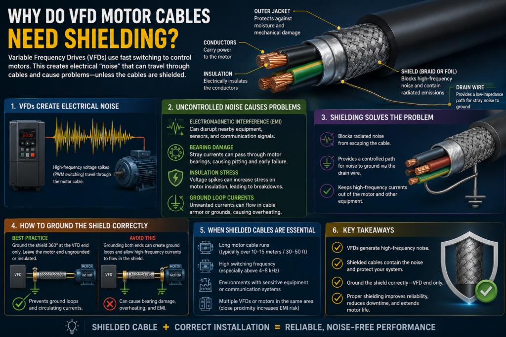
A variable-frequency drive does not feed the motor with a clean 50 or 60 Hz sine wave. It creates its output by switching semiconductor devices on and off thousands of times per second. The resulting pulse-width-modulated voltage contains extremely fast edges and substantial high-frequency energy.
A properly selected shielded motor cable contains that electromagnetic energy and provides a controlled path for high-frequency common-mode current to return to the drive.
Without effective shielding and termination, the motor cable can behave like a long transmitting antenna.
Unfortunately, the nearby encoder cable may be a very enthusiastic receiver.
A VFD Output Is Different From Ordinary Mains Power
A motor connected directly to the mains receives three approximately sinusoidal phase voltages.
A VFD works differently.
It normally:
- Rectifies the incoming AC supply into DC.
- Stores energy in its DC-link circuit.
- Rapidly switches the DC voltage across its output terminals.
- Varies the pulse pattern to control motor voltage and frequency.
The motor current may appear reasonably smooth because the motor windings are inductive.
The voltage reaching the cable is not smooth.
A simplified VFD output looks more like this:
Positive DC-bus pulse
↓
Rapid switching edge
↓
Negative DC-bus pulse
↓
Rapid switching edge
↓
Repeated PWM pattern
The average effect produces the magnetic field needed to turn the motor, but each switching transition introduces high-frequency electrical behaviour that does not exist to the same degree in a normal direct-on-line motor circuit.
Siemens describes converter motor cables as strong sources of interference and recommends shielded, low-capacitance motor cables with the shield connected to the drive and motor over a large surface area.
What Is PWM Switching?
PWM means pulse-width modulation.
Rather than reducing voltage smoothly, the VFD applies full-amplitude voltage pulses of different widths.
By changing the pulse timing, the drive controls the fundamental voltage and frequency seen by the motor.
For example, the motor may be operating at an effective output frequency of 30 Hz, while the drive’s transistors are switching at several kilohertz.
That gives the system two very different electrical worlds:
Low-frequency component:
Produces useful motor torque

High-frequency switching component:
Creates EMI, common-mode current and cable stress
The motor needs the first one.
The rest of the machine would generally prefer not to receive the second.
Why Fast Voltage Edges Cause Interference
The rate at which voltage changes is commonly written as:
dV/dtA VFD output can change by hundreds of volts in a very short time.
Those steep edges contain high-frequency energy. At high frequencies, even small, unintended capacitances and inductances become important.
Current can couple through capacitance between:
- Motor phases and the cable shield
- Motor windings and the motor frame
- Motor cable and nearby signal wiring
- Cable conductors and grounded cable trays
- Motor windings and the rotor
- Separate cables running close together
The faster the voltage changes, the greater the tendency for high-frequency currents and electromagnetic fields to appear throughout the installation.
A normal 50 Hz wiring layout may therefore behave quite differently after a VFD is installed.
The copper has not changed.
The frequency content has.
The Motor Cable Can Behave Like an Antenna
A long conductor carrying rapidly changing voltage creates changing electric and magnetic fields.
If the cable is unshielded, those fields can spread into the surrounding space.
Nearby wiring may then pick up unwanted voltage through:
- Capacitive coupling
- Inductive coupling
- Common impedance
- Ground-potential differences
- Radiated electromagnetic energy
The longer the parallel cable routes, the greater the opportunity for coupling.
This is why a machine may work correctly with a short temporary motor cable during commissioning but become unreliable after the final forty-metre cable is installed in a crowded tray.
The VFD did not suddenly become defective.
The installation became a much better radio transmitter.
What Does the Cable Shield Do?
A VFD motor-cable shield surrounds the current-carrying conductors with a conductive layer.
Depending on the cable, this may include:
- Copper braid
- Copper tape
- Aluminium foil combined with braid
- A concentric copper-wire layer
- Another manufacturer-approved shield construction
The shield performs two related jobs.
It contains electromagnetic fields
The conductive screen reduces the amount of high-frequency energy radiated from the phase conductors into nearby equipment and wiring.
It carries high-frequency current
Capacitive current from the motor and cable needs a path back toward the drive.
A properly terminated shield creates a short, low-impedance return route.
Without that route, current may travel through:
- Machine frames
- Building steel
- Encoder shields
- Communication wiring
- Motor bearings
- Gearboxes
- Unplanned protective-conductor paths
ABB states that the motor-cable shield should provide a continuous high-frequency return path and recommends full-surface, 360-degree grounding at cable entries to minimize radio-frequency interference.
Shielding Is Not the Same as Protective Earthing
The motor cable shield and protective-earth conductor are related, but they are not automatically interchangeable.
The protective-earth conductor is primarily installed for electrical safety. It connects exposed conductive parts so faults can be cleared by the protective system.
The shield is primarily part of the drive system’s electromagnetic-compatibility arrangement.
A typical VFD cable may therefore contain:
Three phase conductors:
U, V and W

Protective-earth conductor:
PE

Overall conductive shield:
EMC and high-frequency return path
Some approved cable designs allow the shield or concentric conductors to contribute to protective-earthing requirements, but only when their construction and cross-sectional area satisfy the applicable rules and the drive manufacturer’s instructions.
Do not assume that a thin foil shield replaces a correctly sized PE conductor.
Likewise, installing a green-and-yellow wire beside an unshielded motor cable does not necessarily provide effective high-frequency shielding.
One protects mainly against fault current.
The other controls rapidly changing electromagnetic energy.
Why an Ordinary Earth Wire May Be Poor at High Frequency
At 50 or 60 Hz, a copper grounding conductor may have very low impedance.
At high frequencies, its inductance becomes more significant.
A long, narrow wire can develop substantial impedance to fast-changing current even if a multimeter measures almost zero resistance.
This is why good VFD bonding connections should generally be:
- Short
- Wide
- Direct
- Secure
- Connected over a large surface area
A cable shield surrounding all three phase conductors provides a much better high-frequency return geometry than one long earth wire routed separately.
The shield remains close to the noise source along the entire cable length.
It does not ask the switching current to take a scenic detour through the cabinet.
Common-Mode Current and the Cable Shield
At any instant, the three VFD output phases do not necessarily add to zero relative to earth.
The inverter’s switching states create a rapidly changing average phase-to-earth voltage known as common-mode voltage.
This voltage drives current through the unavoidable capacitance between:
- Cable conductors and shield
- Motor windings and frame
- Stator and rotor
- Motor and surrounding structures
A simplified current path is:
VFD output
↓
Motor cable and winding capacitance
↓
Motor frame or cable shield
↓
Grounding and bonding system
↓
VFD
A correctly terminated shield helps keep that high-frequency current in a predictable loop.
Without good shielding and bonding, the return path spreads across the machine.
That can increase interference and contribute to other problems, including shaft voltage and bearing current.
What Is Electromagnetic Interference?
Electromagnetic interference, or EMI, is unwanted electrical energy that disrupts another circuit or device.
VFD-related EMI may produce symptoms such as:
- Unstable analog signals
- False PLC inputs
- Encoder-count errors
- Communication dropouts
- Random sensor alarms
- Incorrect temperature readings
- Unexpected safety-device faults
- Audio noise
- Display flickering
- Instrument resets
- RCD or ground-fault problems
- Repeated unexplained machine stops
The interference does not always cause a dramatic failure.
A 4–20 mA pressure signal may simply move by a few tenths of a milliamp. An encoder may lose one pulse every few thousand revolutions. A network may report one intermittent fault per shift.
Those are often the most frustrating problems because the machine works almost perfectly.
Almost.
Why Encoder Signals Are Vulnerable
Encoder signals may contain relatively low-voltage, high-speed pulses or digital communication.
Accurate timing is essential.
If electrical noise creates an additional pulse, removes an edge or changes the signal threshold at the wrong moment, the drive or PLC may interpret the motor position incorrectly.
Possible symptoms include:
- Position drift
- Incorrect speed feedback
- Overspeed alarms
- Encoder-loss faults
- Hunting
- Poor low-speed control
- Unstable positioning
- Unexpected machine movement
- Safety-feedback errors
Rockwell Automation warns that EMI can affect motor and feedback performance, and states that effective grounding of the cable shield is required for a reliable encoder signal in its integrated motor-feedback systems.
A motor can tolerate a slightly distorted power waveform and continue turning.
A position-control loop may be less forgiving about one imaginary encoder pulse.
Sensor and Analog-Signal Problems
Industrial sensors commonly produce:
- 0–10 V signals
- 4–20 mA signals
- Thermocouple voltage
- RTD resistance
- Pulse outputs
- Digital communication
Some of these signals are tiny compared with the voltage pulses on a VFD motor cable.
A thermocouple may generate only millivolts.
A nearby motor conductor may be switching hundreds of volts repeatedly.
If the two cables run side by side, the signal cable can pick up electrical noise.
Symptoms may include:
- Temperature values jumping
- Pressure readings fluctuating
- Load-cell instability
- Level measurements changing with motor speed
- Proximity sensors switching falsely
- Analog inputs becoming noisy only while the drive runs
The sensor itself may be healthy.
The cable route may be the real fault.
Why Noise Changes With Motor Speed
A technician may notice that interference appears only at certain motor speeds.
That can happen because changing the VFD output alters:
- Fundamental output frequency
- Pulse pattern
- Motor current
- Cable resonance
- Common-mode current
- Mechanical vibration
- Carrier-frequency behaviour
The machine may be stable at 20 Hz but unreliable at 42 Hz.
That does not necessarily mean the interference frequency is exactly 42 Hz. The entire switching and cable system has changed with the operating point.
This is one reason VFD-related faults can appear strangely selective.
The noise may seem to know the production recipe.
Why Shielded Signal Cable Alone May Not Be Enough
Using shielded encoder and sensor cables is good practice.
It does not excuse poor motor-cable installation.
Think of the problem at its source.
You could try to armour every sensitive cable against an unshielded VFD motor cable radiating across the cabinet.
Or you could first contain the noise where it is produced.
The strongest approach generally combines:
- A correctly shielded motor cable
- Properly shielded signal cables
- Correct shield termination
- Physical separation
- Effective bonding
- Manufacturer-approved routing
EMC is rarely solved by one magic cable.
It is a system.
Correct Shield Termination Matters
A shield is only effective when high-frequency current can enter and leave it through a low-impedance connection.
A technically shielded cable with poor terminations may perform little better than an unshielded one.
The motor-cable shield should normally be bonded:
- At the VFD end
- At the motor end
- Over as much of its circumference as possible
- To clean conductive surfaces
- Using approved EMC clamps or glands
Rockwell Automation instructs installers to connect the motor-cable shield at both the drive and motor frame, using a shield-termination or EMI clamp at the drive.
The objective is a broad connection around the shield.
Not one lonely strand twisted into a long tail.
What Is 360-Degree Shield Termination?
A 360-degree termination contacts the shield around its full circumference.
Common methods include:
- EMC cable glands
- Spring shield clamps
- Conductive gland plates
- Cable clamps on an EMC plate
- Purpose-built shield-termination brackets
A simplified arrangement is:
Cable outer jacket removed locally
↓
Shield exposed around full circumference
↓
EMC clamp grips shield
↓
Clamp bonds directly to grounded metal plate
This produces a short, wide connection with low high-frequency impedance.
ABB and Siemens both recommend large-area or 360-degree shield bonding for motor cables to reduce electromagnetic emissions.
The clamp should contact the conductive shield.
Clamping firmly onto the intact plastic jacket mainly provides mechanical confidence.
Electrically, it achieves very little.
Why a Shield Pigtail Is Often Ineffective
A pigtail is made by twisting the cable shield into a narrow wire and connecting that wire to earth.
It may look neat and show excellent continuity on a multimeter.
At high frequencies, however, the long narrow connection has inductance.
Its impedance can prevent switching current from flowing efficiently into the panel or motor frame.
Compare:
Good high-frequency termination:
Short, wide, 360-degree connection

Poor high-frequency termination:
Long, thin shield pigtail
The pigtail may still provide some low-frequency bonding.
It weakens the shield exactly where VFD noise is most troublesome: at high frequency.
Rockwell Automation describes 360-degree self-terminating connections as a way to maintain effective VFD cable shielding, while Siemens recommends bonding shields through the largest practical surface area.
The cable was manufactured with an entire shield.
Reducing it to one thin wire at the termination rather defeats the effort.
Ground the Shield at Both Ends
For VFD motor cables, the shield is normally bonded at both the drive and motor ends.
This creates a continuous high-frequency return path from the motor back to the inverter.
Some people hesitate because they have heard that cable shields should be grounded at only one end to avoid ground loops.
That advice can apply in certain low-frequency instrumentation arrangements.
It should not be copied blindly to VFD power cables.
A motor-cable shield connected only at one end may reduce some electric-field coupling, but it is much less effective at carrying high-frequency common-mode current back from the motor.
Siemens specifies that motor-cable shields should be connected at both ends over a large surface area, while Rockwell requires connection at both the drive and motor frame.
Always follow the instructions for the particular VFD, motor and cable system.
What About Ground-Potential Differences?
Connecting shields at both ends can allow current to flow when the motor frame and drive cabinet are at different electrical potentials.
The correct solution is not usually to leave the motor-cable shield disconnected.
The installation should have proper equipotential bonding between:
- VFD cabinet
- Motor frame
- Machine frame
- Cable tray
- Relevant grounded structures
Good bonding reduces the voltage difference and provides controlled current paths.
Where substantial potential differences exist across a site, the earthing and bonding system needs proper engineering.
A shield should not be expected to compensate for two buildings that disagree electrically about where ground is.
Keep the Shield Continuous
The shield should remain electrically continuous from the VFD to the motor.
Problems often appear where the motor cable passes through:
- Local isolators
- Safety switches
- Contactors
- Junction boxes
- Plug connectors
- Terminal boxes
- Cable transitions
If the cable enters an isolator with its shield bonded correctly, then leaves through a second cable whose shield is left floating, the high-frequency path has been interrupted.
ABB recommends metal enclosures and continuous 360-degree grounding of incoming and outgoing shields where switches, contactors or junction boxes are installed between the drive and motor.
At each interruption, the design must preserve:
- Shield continuity
- Short bonding paths
- Conductive enclosure connection
- Protective-earth continuity
- Suitable component ratings
A plastic switch enclosure can create a substantial gap in an otherwise excellent EMC installation unless the manufacturer provides a suitable termination method.
Do Not Switch a VFD Output Casually
A contactor or isolator between a VFD and motor may be necessary for a particular machine design.
It must be selected and controlled according to the VFD manufacturer’s instructions.
Opening or closing the motor circuit while the drive is actively producing output can cause:
- Overvoltage
- Drive faults
- Contact arcing
- Component stress
- Loss of shield continuity
- Unexpected motor behaviour
This is separate from the shielding issue, but both concerns often meet inside the same local motor isolator.
A device can be electrically rated for 400 V and still be installed badly from an EMC perspective.
Voltage rating is not a shield-termination strategy.
Keep Unshielded Tails Short
The shield must usually be removed for the phase conductors to reach terminals.
That exposed section should be kept as short as practical.
Long unshielded tails at the VFD or motor allow high-frequency fields to escape near the termination.
A good installation brings the cable shield close to:
- The drive’s output terminals
- The motor terminal box
- The EMC gland plate
- The shield clamp
Then only the minimum conductor length remains unshielded.
Avoid stripping half a metre of cable because it makes wiring more comfortable.
Comfort during installation can become three years of encoder faults.
The Motor Terminal Box Must Be Bonded
At the motor end, the shield should be bonded to the motor frame through a suitable EMC gland, clamp or manufacturer-approved connector.
Potential problems include:
- Plastic cable glands
- Painted contact surfaces
- Corroded terminal boxes
- Loose EMC clamps
- Shield cut off before entering the box
- Long pigtail connections
- Insulating sealants under the gland
- Replacement motors with different entry hardware
Paint is useful for stopping rust.
It is less useful between two surfaces expected to carry high-frequency current.
Connections should contact clean conductive metal while maintaining the motor’s required environmental protection.
Cable Construction Matters
Not every cable with metallic material inside it is automatically suitable for VFD output.
A proper VFD motor cable may be designed with:
- Symmetrical phase-conductor geometry
- Suitable voltage insulation
- A high-coverage shield
- Low transfer impedance
- Suitable PE arrangement
- Controlled capacitance
- Oil, heat or movement resistance as required
Rockwell’s PowerFlex documentation specifies shielded motor-cable constructions and, for certain EMC installations, requires braided shielding with substantial coverage or an equivalent approved shielding method.
Cable selection must also account for:
- Drive voltage
- Motor current
- Cable length
- Switching frequency
- Installation method
- Ambient temperature
- Flexing requirements
- Chemical exposure
- Local electrical standards
A screened microphone cable is shielded.
That does not qualify it to feed a 45 kW motor.
Why Symmetrical Cable Geometry Helps
A symmetrical VFD cable arranges the phase conductors evenly around the centre of the cable.
This helps balance their electromagnetic fields.
A poor arrangement with an asymmetrically placed protective conductor can create uneven magnetic conditions and greater induced voltage in surrounding metalwork.
A purpose-designed cable may use:
- Three symmetrical phase conductors
- Three symmetrically placed earth conductors
- A concentric shield
- A combination of these features
The exact acceptable construction depends on the drive manufacturer and motor size.
Symmetry is not just an aesthetic preference.
At high current and high frequency, cable geometry becomes part of the circuit.
Separate Motor Cables From Signal Wiring
Even a correctly shielded VFD cable should not be bundled with sensitive signal wiring unless the approved system is specifically designed for it.
Keep motor cables separated from:
- Encoder cables
- Analog sensor cables
- Thermocouple wiring
- Load-cell cables
- Ethernet
- PROFINET
- PROFIBUS
- CAN bus
- Safety signals
- Low-voltage control wiring
Siemens recommends dividing cables into appropriate EMC groups, maintaining separation and crossing incompatible cable groups at right angles when a crossing cannot be avoided.
The exact separation distance depends on the equipment, cable construction and manufacturer instructions.
The general rule is simple:
More distance
+
Less parallel routing
=
Less unwanted coupling
Electromagnetic fields weaken with distance.
Occasionally, the cheapest EMC component is empty space.
Avoid Long Parallel Runs
Two cables running beside each other form a better coupling arrangement than two cables that meet briefly.
Long parallel routes increase both capacitive and inductive coupling.
Therefore:
- Do not cable-tie encoder wiring to a VFD motor cable.
- Do not place analog wiring in the same tight bundle.
- Use separate tray sections or metal dividers.
- Keep the routes apart inside the control cabinet.
- Avoid sharing conduit unless specifically permitted.
- Minimize the length over which power and signal cables remain parallel.
Siemens recommends spatial separation between motor cables and signal or data wiring, with grounded metal barriers where sufficient distance cannot be maintained.
A beautifully organized bundle containing every machine cable may look impressive.
Electrically, it can be a group discussion nobody asked for.
Cross at 90 Degrees
Sometimes a signal cable must cross a motor cable.
When that cannot be avoided, cross them as close to a right angle as practical.
At 90 degrees, the length over which the two cables remain close and parallel is minimized.
This reduces coupling compared with allowing them to merge gradually and travel together.
The arrangement should resemble:
Motor cable:
──────────────

Signal cable:
      │
      │
      │
Not:
Motor cable:
──────────────

Signal cable:
   ───────────
Both Siemens and Rockwell guidance emphasize physical separation between power wiring and sensitive signal circuits; Siemens specifically recommends right-angle crossings where cable groups must intersect.
Use Separate Cable-Tray Zones
A well-designed industrial tray may have dedicated areas for:
- VFD motor power
- Fixed-frequency mains power
- 24 V DC control wiring
- Analog signals
- Communication and encoder cables
Metal dividers can provide additional shielding when physical separation is limited.
Tray sections should also be electrically bonded so they do not behave like disconnected pieces of floating metal.
The routing plan should be established before the panel and machine are wired.
Trying to find room for the encoder cable after six motor cables have occupied the entire tray generally leads to creative language and less creative EMC performance.
Keep Motor Cables Away From the PLC Section
Inside a control panel, route VFD output cables away from:
- PLC input modules
- Analog modules
- Communication switches
- Safety controllers
- Encoder interfaces
- Instrumentation terminals
Where possible, keep noisy power equipment and sensitive control equipment in different cabinet zones.
Shield clamps should connect directly to a conductive mounting plate or shield bar near the cable entry.
Do not route the unshielded motor leads across the PLC rack before reaching the VFD.
The drive output cable should leave the noisy section quickly and directly.
The PLC has enough work already.
Input Cables and Output Cables Are Not the Same
The VFD input cable carries mains-frequency power with some harmonic current.
The output cable carries high-frequency PWM voltage.
They therefore have different interference characteristics.
Do not route the VFD input and motor output tightly together over long distances.
Noise from the output side can couple back into the supply wiring and bypass filters intended to control conducted emissions.
Filtered input wiring should also be separated from unfiltered wiring where the manufacturer requires it.
A drive can be fitted with an excellent EMC filter and still fail EMC expectations because the filtered and noisy cables spend the next two metres sharing an intimate cable bundle.
Cable Length Can Increase the Problem
Long motor cables have more capacitance between their conductors and shield.
The VFD must charge and discharge that capacitance during every switching transition.
As cable length increases, the system may experience:
- Greater common-mode current
- Higher drive loading
- More electromagnetic emission
- Motor-terminal voltage reflections
- Increased insulation stress
- Greater risk of nuisance trips
- Additional bearing-current concerns
Every VFD has cable-length limitations or application guidance.
Long runs may require:
- Reduced carrier frequency
- A dV/dt filter
- A sine-wave filter
- An output reactor
- A different cable type
- Drive derating
- Manufacturer review
Shielding controls emissions.
It does not remove every electrical effect created by a long PWM cable.
Metal Conduit Versus Shielded Cable
Some drive installations permit properly installed metallic conduit as an alternative or part of the shielding system.
The conduit must provide:
- Reliable electrical continuity
- Low-impedance bonding
- Suitable connections at both ends
- Proper fittings at junctions
- Compliance with the drive documentation
Flexible conduit sections, painted joints or loose locknuts can weaken the high-frequency path.
Rockwell’s EMC documentation permits specified shielded cable, metal conduit or equivalent shielding for certain PowerFlex installations.
This does not mean every random length of steel conduit automatically performs like a purpose-designed VFD cable.
The entire enclosure and bonding path matters.
Why Ferrites Alone Do Not Replace Shielding
Ferrite cores and common-mode chokes can reduce certain high-frequency currents.
They may be useful additions where the manufacturer recommends them.
They do not normally replace:
- Correct cable type
- Full shield termination
- Proper bonding
- Cable separation
- Suitable routing
A ferrite installed around an unshielded, badly routed motor cable may reduce one frequency range while leaving the larger installation problem untouched.
The order should usually be:
- Install the cable correctly.
- Terminate the shield correctly.
- Route and separate wiring correctly.
- Add approved filtering if still required.
Filters are easier to appreciate after the basic mistakes have stopped shouting.
Why Shield Connections Deteriorate
An installation that worked correctly when new may develop EMI problems later.
Shield performance can deteriorate because of:
- Corrosion
- Loose cable glands
- Vibration
- Paint after maintenance
- Replaced motors
- Damaged cable braid
- Broken conduit bonding
- Modified junction boxes
- Oil or contamination
- Improvised cable repairs
A motor replacement is a common turning point.
The original motor may have used a metal EMC gland. The replacement is wired through an ordinary plastic gland, with the cable shield cut back and taped neatly out of sight.
Mechanically tidy.
Electromagnetically missing.
Common VFD Cable-Shielding Myths
“The motor runs, so the cable is suitable”
Not necessarily.
An unsuitable cable may still deliver motor current while radiating interference or overstressing other parts of the system.
“The PE conductor provides all the shielding required”
No.
Protective earth is essential, but an overall shield provides a much better high-frequency containment and return geometry.
“Grounding the shield at one end prevents all ground loops”
That advice should not be applied automatically to VFD motor cables. Drive manufacturers generally require motor-cable shields to be bonded at both ends.
“A shield pigtail is as good as a 360-degree clamp”
No.
The pigtail’s inductance reduces its effectiveness at high frequency.
“Shielded cable means it can be routed beside encoder wiring”
No.
Shielding reduces emissions; physical separation provides another necessary layer of protection.
“Foil is always as effective as braid”
Not necessarily.
Shield performance depends on coverage, transfer impedance, termination and frequency. Use the cable construction specified by the drive manufacturer.
“Cable armour automatically makes a perfect VFD shield”
Not always.
Armour construction and termination may not provide the required high-frequency performance.
“Only large motors need shielded cable”
Small drives can still disturb encoders, analog sensors and communication networks. The required EMC precautions depend on the whole installation, not merely motor power.
“A shield fixes poor grounding”
No.
Shielding, protective earthing and equipotential bonding must work together.
A Practical Installation Checklist
Before commissioning a VFD motor circuit, verify that:
- The cable is approved for PWM drive output.
- Cable voltage and current ratings are correct.
- The shield construction meets the VFD manufacturer’s requirements.
- The cable length remains within specified limits.
- A separate or approved protective-earth path is present.
- The shield is bonded at the VFD end.
- The shield is bonded at the motor end.
- Both terminations use large-area or 360-degree contact.
- Long shield pigtails are avoided.
- Unshielded conductor tails are kept short.
- Paint is removed where conductive bonding is required.
- The motor frame is properly bonded.
- The drive cabinet and machine frame are correctly bonded.
- Shield continuity is maintained through isolators and junction boxes.
- Motor wiring is separated from encoder and sensor wiring.
- Signal and motor cables cross at 90 degrees when necessary.
- Analog and communication cables use their specified shielding.
- Input and output drive cables are routed separately.
- Cable trays and metal conduit sections are electrically continuous.
- Filters or reactors are installed when cable length requires them.
Installation details should follow the manuals for the specific VFD, motor and cable rather than a generic diagram found beside a suspiciously confident forum comment.
Troubleshooting Suspected VFD Interference
When a machine develops noise-related problems, note whether the fault changes when:
- The VFD is stopped
- The motor cable is disconnected safely
- Motor speed changes
- Carrier frequency changes
- The encoder cable is moved temporarily
- Signal wiring is separated from the motor cable
- Shield clamps are repaired
- A temporary bonding strap is installed by qualified personnel
- The machine operates from direct mains instead of the drive, where designed for this
- Communication cables are rerouted
Inspect:
- Both motor-cable shield terminations
- Motor terminal-box gland
- VFD shield clamp
- Cable damage
- Junction-box continuity
- Local isolator construction
- Machine bonding
- Signal-cable routing
- Encoder shield connections
Do not change grounding or drive settings randomly while the machine is operating.
EMC fault-finding should be controlled and documented.
Otherwise, one accidental improvement may disappear before anyone learns why it worked.
Safety Before Working on VFD Cables
A stopped motor does not prove that the VFD is electrically safe.
The drive’s DC-link capacitors may retain dangerous voltage after the incoming supply is disconnected.
Before inspecting or modifying the motor cable:
- Stop the machine safely.
- Isolate all power sources.
- Apply lockout and tagout procedures.
- Wait for the manufacturer’s stated discharge time.
- Verify absence of voltage using suitable equipment.
- Check for auxiliary, generator or regenerated supplies.
- Follow the drive manufacturer’s safety instructions.
Do not disconnect cable shields, open motor terminals or move conductors while the VFD is energized.
The high-frequency noise may be annoying.
The DC bus is less interested in merely being annoying.
The Practical Answer
So, why use shielded cable for a VFD?
Because a VFD motor cable carries rapidly switched PWM voltage rather than a smooth mains-frequency waveform.
Those fast voltage edges produce high-frequency electromagnetic fields and common-mode currents. An unshielded cable can radiate that energy into nearby encoder, sensor, PLC and communication wiring.
A properly selected shielded motor cable:
- Contains electromagnetic emissions
- Provides a controlled high-frequency return path
- Reduces interference with nearby equipment
- Helps the installation meet the drive manufacturer’s EMC requirements
- Limits unintended current through machine structures and other wiring
The shield must be installed correctly.
That normally means:
360-degree termination at the VFD
+
360-degree termination at the motor
+
Grounding at both ends
+
Continuous shielding
+
Physical separation from signal cables
A long pigtail connection may look grounded while performing poorly at PWM frequencies. Leaving the motor-end shield disconnected removes an important high-frequency return path. Bundling the finished motor cable with an encoder cable invites the noise back into the system.
Shielding is not magic foil hidden inside a cable.
It is a complete path from the drive to the motor.
When that path is designed, terminated and routed correctly, the motor receives its controlled power while the sensors are allowed to continue reporting reality.