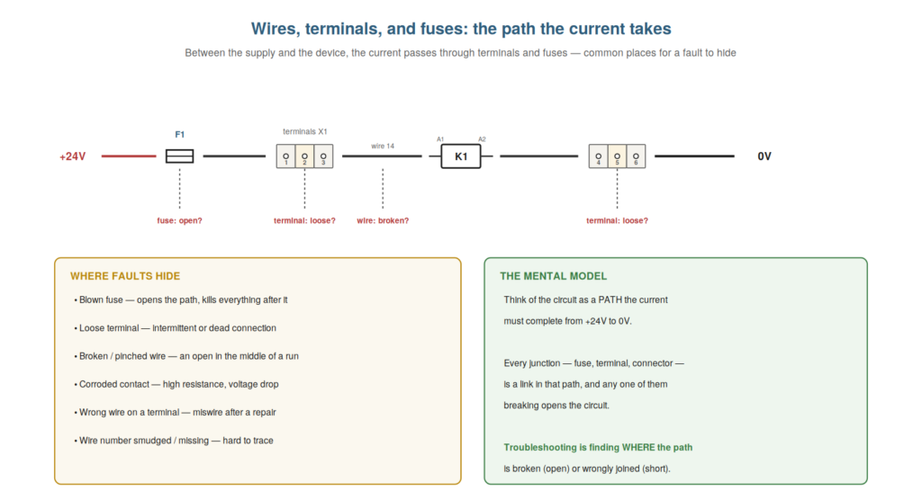
Between the power supply and the devices it feeds, the current travels through wires, terminals, and fuses — the connective tissue of the circuit — and understanding these, along with the faults that hide in them, is fundamental to control-circuit troubleshooting. These are simple components, but they are where a great many faults occur: a blown fuse, a loose terminal, a broken wire. This chapter covers wires, terminals, and fuses and the mental model of the circuit as a path, which is central to everything that follows.

The circuit as a path
The single most important mental model in control-circuit troubleshooting is the circuit as a path, and understanding it shapes how you think about every fault. Picture the current as needing to complete a journey: from the +24V rail, through a series of components — fuse, terminal, wire, contact, device — to the 0V rail, forming a complete path. The device operates only when this path is complete, allowing current to flow. Every component in the path is a link in the chain, and the chain works only if every link is intact. This model turns troubleshooting into a clear question: where is the path broken (an open, so current cannot flow) or wrongly joined (a short, so current takes an unintended route)? So the circuit-as-a-path model frames every fault as a break or an unwanted connection in the path the current must complete. Understanding this model — the circuit as a path the current completes, a fault as a break or unwanted join in it — shapes how you approach every fault. It reinforces that the circuit is a path from +24V to 0V through a series of links, and a fault is a break (open) or unwanted connection (short) in that path. Understanding the circuit as a path — the current completing a journey from +24V through a series of components to 0V, with a fault being a break in that path (an open) or an unwanted connection across it (a short) — is the single most important mental model in control-circuit troubleshooting, because it frames every fault as a clear question of where the path is broken or wrongly joined, which turns the abstract problem of a misbehaving circuit into the concrete task of locating the break or the unwanted connection in a path you can trace and measure, the foundation of the systematic methods this book teaches.
Fuses: protection and a common open
Fuses deserve particular understanding, because they are both the circuit’s protection and one of the most common causes of an open, and knowing how they work directs a frequent diagnosis. A fuse is a deliberate weak link: it carries the normal current, but if the current exceeds its rating (from a short or overload), the fuse element melts and opens, breaking the circuit to protect the wiring and devices from the excess current. So a fuse protects by opening under excess current. This makes a blown fuse a very common open: when a fuse blows, everything downstream of it goes dead, and finding the blown fuse explains the dead circuit. But crucially, a fuse blows for a reason — usually a fault caused the excess current — so a blown fuse is a clue, not just a part to replace: refitting it without finding why it blew often just blows the new fuse. So understanding fuses — protection by opening, a common cause of a dead circuit, and a clue to a deeper fault — directs both the finding and the proper resolution of a frequent fault. Understanding fuses — the deliberate weak link that opens under excess current, protecting the circuit — explains a very common open and a clue to a deeper fault. Understanding fuses as both protection and a common open — the weak link that opens under excess current to protect the circuit, making a blown fuse a frequent cause of a dead downstream circuit and a clue to why the excess current occurred — directs a common diagnosis, so that when you find a blown fuse you both explain the dead circuit and know to ask why it blew before refitting, because a fuse blows for a reason (usually a fault drawing excess current), and simply replacing it without finding the cause often just blows the new one, making the fuse a protection device, a common fault location, and an important clue all at once.
Terminals and wires: quiet fault locations
Terminals and wires are quiet, easily-overlooked fault locations, and understanding the faults that occur there — and why — helps you inspect and suspect them appropriately. A terminal is a connection point where wires join, and it can fail in ways that break or degrade the path: a terminal screw can work loose (from vibration), making an intermittent or high-resistance connection; a wire can back out of a terminal; a terminal can corrode. A wire, too, can fail: it can break (especially where it flexes, in a cable chain or at a bend), get pinched or crushed (by a moving part or a closing door), or its insulation can chafe through. These faults are quiet because they are not obvious — a loose terminal or a broken strand inside insulation looks fine — yet they open or degrade the path. Understanding that terminals and wires fail in these ways, particularly at points of vibration and flexing, helps you inspect and suspect them: check terminals for tightness, examine wires at flex points. So terminals and wires are quiet fault locations that understanding helps you attend to. Understanding terminals and wires as quiet fault locations — loose or corroded terminals, broken or pinched wires, especially at vibration and flex points — helps you inspect and suspect them appropriately. Understanding terminals and wires as quiet fault locations — the loose or corroded terminals and the broken, pinched, or chafed wires that open or degrade the path without being obvious, particularly at points of vibration and flexing — helps you inspect and suspect them appropriately, so that you know to check terminals for tightness and examine wires where they flex or could be pinched, attending to these easily-overlooked but common fault locations that quietly break the path the current must complete, which is where a substantial share of real control-circuit faults are found once you know to look.
Different fuses for different jobs
A practical detail is that different fuses suit different jobs, and understanding the main distinctions helps you replace a fuse correctly and reason about why one blew. Fuses differ in rating (the current they carry before blowing) and in speed (how quickly they blow): a fast-acting fuse blows quickly on excess current, protecting sensitive circuits, while a time-delay (slow-blow) fuse tolerates a brief surge before blowing, suiting loads with an inrush current. Replacing a fuse with the wrong rating or type causes problems: too high a rating fails to protect, too low or too fast blows on normal operation (nuisance blowing), too slow may not protect adequately. So you replace a fuse with the same rating and type as specified. Understanding these distinctions also helps reason about a blowing fuse: a fuse blowing on a load’s inrush might be the wrong (too fast) type, while one blowing outright signals a real fault. So understanding different fuses — rating and speed — helps you replace correctly and reason about blowing. Understanding that different fuses suit different jobs — differing in current rating and in speed (fast-acting versus time-delay) — helps you replace a fuse correctly with the specified rating and type and reason about why one blew, so that you avoid the problems of a wrong replacement (too high failing to protect, too fast nuisance-blowing, too slow under-protecting) and can interpret a blowing fuse correctly (a nuisance blow on inrush suggesting a wrong-type fuse, an outright blow signaling a real fault), which makes the humble fuse’s specifications a practical part of both correct replacement and accurate diagnosis.
Scenario: the loose terminal
A scenario shows the circuit-as-a-path model and terminal awareness solving a fault. A device worked unreliably — sometimes on, sometimes not — and the technician thought of the circuit as a path the current must complete, asking where a link might be failing. Knowing terminals are quiet fault locations that vibrate loose, he inspected the terminals along the path and found one that was loose — the screw had backed off with vibration, making an intermittent, high-resistance connection. When the machine vibrated, the loose terminal broke contact, opening the path and stopping the device; when still, it made contact again. Tightening the terminal (and checking the others) restored reliable operation. The path model told him to look for a failing link, and terminal awareness told him where. This scenario shows the path model and terminal awareness solving an intermittent. Understanding the circuit as a path and terminals as quiet fault locations let the technician find the loose terminal breaking the path. It reinforces that thinking of the circuit as a path and knowing terminals vibrate loose leads you to the failing link. The scenario reinforces the path model and terminal awareness: the technician solved an unreliable device by thinking of the circuit as a path with a failing link and knowing terminals vibrate loose, finding the loose terminal that intermittently opened the path, illustrating how the circuit-as-a-path mental model plus awareness of where faults hide (terminals, at vibration) leads efficiently to the quiet connection faults that cause so much trouble.
Ferrules, labels, and good terminations
A practical detail worth understanding is what makes a good termination — ferrules, labels, and proper technique — because good terminations prevent faults and poor ones cause them. A quality termination in a control panel typically uses a ferrule (a metal sleeve crimped onto the stripped wire end) that gives the stranded wire a solid, consistent end to clamp in the terminal, preventing loose strands and ensuring a reliable connection; a wire label or ferrule marked with the wire number links it to the schematic; and proper technique (correct strip length, correct crimp, correct torque on the terminal screw) ensures the connection is sound. Poor terminations — no ferrule so strands splay and some are missed, over- or under-tightened screws, wrong strip length — cause the loose and high-resistance connections that plague control circuits. Understanding what a good termination looks like helps you both recognize a poor one (a likely fault) and make a proper repair (a ferrule, correct torque, a label). So understanding ferrules, labels, and good terminations helps you spot and make sound connections. Understanding ferrules, labels, and good terminations — the crimped ferrule giving stranded wire a solid end, the label linking it to the schematic, and the proper strip-crimp-torque technique — helps you both recognize a poor termination as a likely fault and make a proper repair, so that you can spot the missing ferrule, splayed strands, or wrong torque behind a loose or high-resistance connection and remake it soundly with a ferrule, correct technique, and a label, which addresses the terminations that are among the most common quiet fault locations and ensures your own repairs do not become the next fault.
The path model as your foundation
To close, it is worth emphasizing that the circuit-as-a-path model is the foundation the whole book builds on, because holding it firmly makes every later method make sense. The path model — current completing a journey from +24V to 0V, a fault being a break (open) or unwanted join (short) in that path — is not just this chapter’s idea; it is the frame for the dead circuit, the open, the short, voltage tracing, divide and conquer, and the whole diagnostic approach. Every method in the book is, at heart, about finding where the path is broken or wrongly joined. So the path model is the foundation, and holding it firmly is what makes the later methods coherent rather than a bag of tricks. Understanding the path model as your foundation — the frame every later method builds on — makes the whole diagnostic approach coherent. Understanding the circuit-as-a-path model as your foundation — the frame that every later method (the dead circuit, opens, shorts, voltage tracing, divide and conquer) builds upon, all of them about finding where the path is broken or wrongly joined — makes the whole book’s diagnostic approach coherent, so that you hold the path model firmly as the single idea underlying every technique, which turns the book’s methods from a collection of separate tricks into a unified approach grounded in the one foundational picture of the circuit as a path the current must complete, the deeper value of the model this chapter introduces.