Cable Construction and Pairing
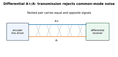
Encoder cables often contain twisted signal pairs, power conductors, shield/drain, and sometimes individually shielded pairs. Replacing them with generic multicore cable can increase capacitance and destroy differential pair geometry.
What to Check
- Identify the original cable specification.
- Confirm twisted pairs are maintained end to end.
- Check conductor gauge and flex rating for moving applications.
Diagnostic Sequence
- Compare signal at encoder and receiver.
- Temporarily use a known-good encoder cable routed safely away from power.
- Check for repaired sections where pair assignments changed.
Common Mistakes
- Using any spare screened cable.
- Untwisting pairs for long distances inside cabinets.
- Mixing A+ with B- in the same twisted pair.
Field Rule: Cable geometry is part of the electrical interface.
Shield Termination
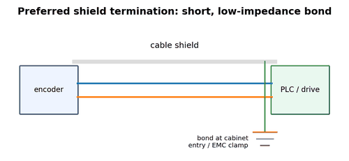
A cable shield intercepts high-frequency electric fields and gives noise current a controlled return path. For encoder systems, the termination method should follow the equipment manufacturer and site EMC design. A short, low-impedance 360-degree bond at cabinet entry is commonly preferred over a long pigtail for high-frequency noise.
What to Check
- Inspect where the shield is bonded.
- Check for long unshielded tails at VFD cabinets.
- Verify shield continuity through connectors if designed that way.
Diagnostic Sequence
- Compare noise before and after correcting a poor bond.
- Use temporary EMC clamps only as a controlled diagnostic.
- Document the final grounding method.
Common Mistakes
- Connecting shield to a random 0 V terminal.
- Leaving shield floating when the design requires bonding.
- Using long thin pigtails near high-frequency drive cables.
Field Rule: At high frequency, bond length matters as much as continuity.
Ground Loops and Potential Differences
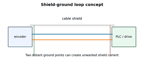
Shielding and signal reference are related but not identical. Machines spanning large distances may have different ground potentials. Improper bonding can drive current through shields or signal commons. The goal is an intentional equipotential bonding system and an interface suitable for the environment.
What to Check
- Measure unexpected AC/DC voltage between machine sections.
- Inspect protective bonding straps and cabinet earth connections.
- Check whether signal 0 V is being used as a substitute for PE.
Diagnostic Sequence
- Correct protective bonding faults according to site electrical practice.
- Use differential interfaces or isolation where specified.
- Do not “solve” a ground problem by removing safety earth conductors.
Common Mistakes
- Disconnecting protective earth to stop noise.
- Confusing cable shield with protective conductor.
- Adding random earth links without understanding the plant bonding scheme.
Field Rule: Never trade electrical safety for a cleaner signal.
Separation from VFD Motor Cables
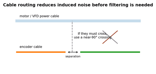
PWM motor cables carry fast voltage edges and high common-mode currents. Long parallel runs beside encoder cable are a common source of false counts and drive feedback alarms.
What to Check
- Inspect tray and conduit routes from encoder to cabinet.
- Look for sections tied directly to motor leads.
- Check crossing angles and separation.
Diagnostic Sequence
- Re-route a temporary cable away from VFD output as a diagnostic.
- If the fault improves, correct routing and shielding before adding filters.
- Check VFD motor cable shield termination as part of the EMC system.
Common Mistakes
- Running all cables together because they are shielded.
- Crossing at shallow angles for long distances.
- Focusing only on the encoder shield while motor cable bonding is poor.
Field Rule: Prevent noise coupling physically before trying to filter it electronically.
Moving Cable and Drag-Chain Faults
Continuous-flex applications break conductors internally long before the outer jacket looks damaged. The encoder may fail only at one carriage position or during acceleration.
What to Check
- Ask whether the fault occurs at a repeatable axis position.
- Inspect bend radius and drag-chain fill.
- Check for unsupported connector transitions.
Diagnostic Sequence
- Monitor continuity while slowly flexing an isolated cable.
- Trend raw encoder counts versus axis position.
- Replace with the correct continuous-flex cable if damage is confirmed.
Common Mistakes
- Using a standard stationary cable in a drag chain.
- Bending at the connector gland.
- Relying on static continuity tests only.
Field Rule: Position-dependent intermittent faults strongly suggest moving-cable damage.
Connector Pin and Contact Problems
Small encoder contacts carry little current, so corrosion or fretting can produce high resistance without obvious heating. Vibration can make a marginal pin open for milliseconds.
What to Check
- Inspect pin seating and backshell strain relief.
- Look for pushed-back contacts and cracked solder joints.
- Check connector locking mechanism.
Diagnostic Sequence
- Use a breakout adapter when available.
- Monitor signal while gently moving the cable outside the guarded machine area.
- Compare voltage drop across suspect connector sections.
Common Mistakes
- Probing from the front and spreading female contacts.
- Packing connectors with inappropriate grease.
- Ignoring connector keying after replacing an extension cable.
Field Rule: A millisecond contact interruption can create a machine fault even if the meter later reads continuity.
Cable Capacitance and Rise Time
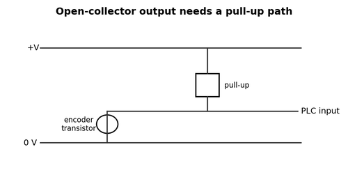
Long cables add capacitance. With open-collector outputs, the pull-up resistor and cable capacitance form an RC circuit that slows the rising edge. At high frequency the signal may never reach a valid high level before the next transition.
What to Check
- Estimate cable length and output type.
- Observe rise time at the receiver.
- Compare with input threshold and pulse period.
Diagnostic Sequence
- Try the specified pull-up value for the cable length.
- Use a line-driver interface where appropriate.
- Reduce unnecessary cable length and stubs.
Common Mistakes
- Selecting pull-up resistance by DC current only.
- Adding long tee branches.
- Ignoring edge rate because frequency looks correct at low speed.
Field Rule: High-speed digital problems are often edge-time problems, not just voltage problems.
Splices, Junction Boxes, and Stubs
Every splice adds contact resistance, possible pair untwist, shield discontinuity, and impedance change. A short stub to a test connector can reflect or distort fast differential edges on long runs.
What to Check
- Count every connector and junction between encoder and receiver.
- Inspect shield continuity through junctions.
- Check pair assignments after field repairs.
Diagnostic Sequence
- Bypass suspect junctions with a direct temporary cable.
- Compare waveform before and after the junction.
- Remove unused stubs if not required.
Common Mistakes
- Leaving old test stubs connected permanently.
- Terminating shield only with thin drain wires through junctions.
- Using mixed connector families with improvised pinouts.
Field Rule: Simplify the signal path when chasing an intermittent encoder fault.
Common-Mode Noise
Noise coupled equally onto both wires of a differential pair is common-mode noise. A healthy differential receiver rejects much of it, but only within its common-mode voltage range and with balanced wiring.
What to Check
- Measure both sides of the pair relative to reference if safe.
- Inspect pair symmetry and shield.
- Check grounding between encoder and receiver.
Diagnostic Sequence
- If differential voltage is good but each conductor is far outside receiver common-mode range, correct grounding/interface.
- Use proper differential measurement techniques.
- Check for damaged line receivers after severe transients.
Common Mistakes
- Assuming differential means unlimited noise immunity.
- Connecting one side of the pair to ground.
- Using unmatched conductors that destroy balance.
Field Rule: Differential reception rejects common noise only while the receiver remains inside its operating range.
EMC Troubleshooting Sequence
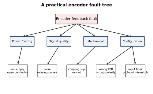
Noise problems become chaotic when many changes are made at once. A disciplined sequence identifies the coupling path and preserves evidence.
What to Check
- Record when counts fail: drive switching, contactor opening, welding, brake release, high speed.
- Check cable route, shield bond, pair integrity, and grounding.
- Capture waveform at receiver.
Diagnostic Sequence
- Change one variable at a time.
- Use a temporary clean route as a strong A/B comparison.
- Return test modifications to a documented safe final configuration.
Common Mistakes
- Adding ferrites, filters, grounds, and software delays simultaneously.
- Leaving temporary ground clips installed.
- Calling a fault “EMI” without reproducing it.
Field Rule: An EMC fix is strongest when you can show which coupling path was removed.