By Dovydas Kersys · Chapter 6 of 12 in Pneumatic Troubleshooting.
Before you begin: The diagrams are simplified teaching illustrations. Verify the actual machine schematic and component documentation. Isolate and control stored energy before intrusive work, and use the approved machine procedure for any energized measurements. Compressed air must not be the sole support for a load where unexpected movement could cause injury.
PLC Output to Motion
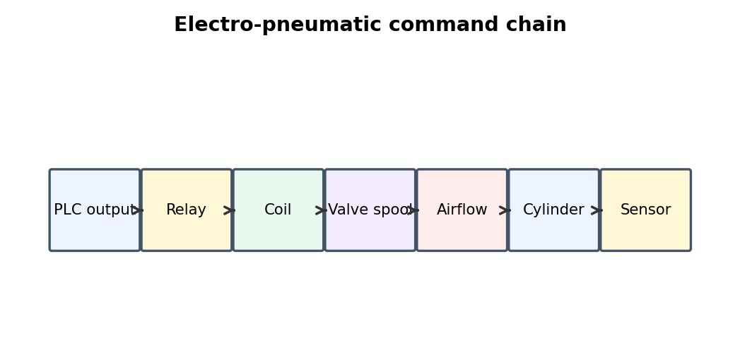
The PLC command is only the first link in a chain that ends with physical actuator motion and sensor confirmation. Electro-pneumatic faults cross the boundary between PLC logic and air power, so the command must be traced from the controller all the way to physical motion and back to sensor feedback.
What to check
- Monitor PLC output and actual field voltage.
- Measure coil voltage with the coil connected.
- Check relay/connector voltage drop.
- Verify valve work-port pressure changes and final sensor state.
Diagnostic sequence
- Start at the PLC or relay command.
- Move one stage toward the actuator until expected behavior disappears.
- Repair that stage.
- Verify final pneumatic motion and sensor feedback through repeated cycles.
Common mistakes
Assuming PLC bit ON means the coil is powered. • Assuming relay LED means the contact is good. • Changing PLC logic before proving hardware.
FIELD RULE: Trace the command chain one link at a time.
24 VDC Coil Undervoltage
Loose terminals, weak power supplies, relay contact resistance, or shared return problems can reduce solenoid voltage under load. Electro-pneumatic faults cross the boundary between PLC logic and air power, so the command must be traced from the controller all the way to physical motion and back to sensor feedback.
What to check
- Monitor PLC output and actual field voltage.
- Measure coil voltage with the coil connected.
- Check relay/connector voltage drop.
- Verify valve work-port pressure changes and final sensor state.
Diagnostic sequence
- Start at the PLC or relay command.
- Move one stage toward the actuator until expected behavior disappears.
- Repair that stage.
- Verify final pneumatic motion and sensor feedback through repeated cycles.
Common mistakes
Assuming PLC bit ON means the coil is powered. • Assuming relay LED means the contact is good. • Changing PLC logic before proving hardware.
FIELD RULE: Trace the command chain one link at a time.
Valve Chatter
Rapid valve switching can start electrically with unstable voltage or pneumatically with low pilot pressure and sticking. Electro-pneumatic faults cross the boundary between PLC logic and air power, so the command must be traced from the controller all the way to physical motion and back to sensor feedback.
What to check
- Monitor PLC output and actual field voltage.
- Measure coil voltage with the coil connected.
- Check relay/connector voltage drop.
- Verify valve work-port pressure changes and final sensor state.
Diagnostic sequence
- Start at the PLC or relay command.
- Move one stage toward the actuator until expected behavior disappears.
- Repair that stage.
- Verify final pneumatic motion and sensor feedback through repeated cycles.
Common mistakes
Assuming PLC bit ON means the coil is powered. • Assuming relay LED means the contact is good. • Changing PLC logic before proving hardware.
FIELD RULE: Trace the command chain one link at a time.
Reed Switches
Reed switches can become intermittent, welded, or mispositioned and should be tested against real piston position. Electro-pneumatic faults cross the boundary between PLC logic and air power, so the command must be traced from the controller all the way to physical motion and back to sensor feedback.
What to check
- Monitor PLC output and actual field voltage.
- Measure coil voltage with the coil connected.
- Check relay/connector voltage drop.
- Verify valve work-port pressure changes and final sensor state.
Diagnostic sequence
- Start at the PLC or relay command.
- Move one stage toward the actuator until expected behavior disappears.
- Repair that stage.
- Verify final pneumatic motion and sensor feedback through repeated cycles.
Common mistakes
Assuming PLC bit ON means the coil is powered. • Assuming relay LED means the contact is good. • Changing PLC logic before proving hardware.
FIELD RULE: Trace the command chain one link at a time.
Solid-State Cylinder Sensors
PNP, NPN, two-wire, and three-wire sensors require the correct PLC input interface and supply polarity. Electro-pneumatic faults cross the boundary between PLC logic and air power, so the command must be traced from the controller all the way to physical motion and back to sensor feedback.
What to check
- Monitor PLC output and actual field voltage.
- Measure coil voltage with the coil connected.
- Check relay/connector voltage drop.
- Verify valve work-port pressure changes and final sensor state.
Diagnostic sequence
- Start at the PLC or relay command.
- Move one stage toward the actuator until expected behavior disappears.
- Repair that stage.
- Verify final pneumatic motion and sensor feedback through repeated cycles.
Common mistakes
Assuming PLC bit ON means the coil is powered. • Assuming relay LED means the contact is good. • Changing PLC logic before proving hardware.
FIELD RULE: Trace the command chain one link at a time.
Pressure Switches and Transducers
A blocked sensing port or bad setpoint can create control faults even when the pneumatic circuit is healthy. Electro-pneumatic faults cross the boundary between PLC logic and air power, so the command must be traced from the controller all the way to physical motion and back to sensor feedback.
What to check
- Monitor PLC output and actual field voltage.
- Measure coil voltage with the coil connected.
- Check relay/connector voltage drop.
- Verify valve work-port pressure changes and final sensor state.
Diagnostic sequence
- Start at the PLC or relay command.
- Move one stage toward the actuator until expected behavior disappears.
- Repair that stage.
- Verify final pneumatic motion and sensor feedback through repeated cycles.
Common mistakes
Assuming PLC bit ON means the coil is powered. • Assuming relay LED means the contact is good. • Changing PLC logic before proving hardware.
FIELD RULE: Trace the command chain one link at a time.
Vacuum Switches
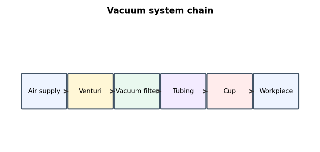
Vacuum confirmation must reflect a genuinely safe holding condition rather than a lowered threshold hiding weak vacuum. Electro-pneumatic faults cross the boundary between PLC logic and air power, so the command must be traced from the controller all the way to physical motion and back to sensor feedback.
What to check
- Monitor PLC output and actual field voltage.
- Measure coil voltage with the coil connected.
- Check relay/connector voltage drop.
- Verify valve work-port pressure changes and final sensor state.
Diagnostic sequence
- Start at the PLC or relay command.
- Move one stage toward the actuator until expected behavior disappears.
- Repair that stage.
- Verify final pneumatic motion and sensor feedback through repeated cycles.
Common mistakes
Assuming PLC bit ON means the coil is powered. • Assuming relay LED means the contact is good. • Changing PLC logic before proving hardware.
FIELD RULE: Trace the command chain one link at a time.
Interposing Relays
A relay may click and light its LED while a burned contact still drops most of the coil voltage. Electro-pneumatic faults cross the boundary between PLC logic and air power, so the command must be traced from the controller all the way to physical motion and back to sensor feedback.
What to check
- Monitor PLC output and actual field voltage.
- Measure coil voltage with the coil connected.
- Check relay/connector voltage drop.
- Verify valve work-port pressure changes and final sensor state.
Diagnostic sequence
- Start at the PLC or relay command.
- Move one stage toward the actuator until expected behavior disappears.
- Repair that stage.
- Verify final pneumatic motion and sensor feedback through repeated cycles.
Common mistakes
Assuming PLC bit ON means the coil is powered. • Assuming relay LED means the contact is good. • Changing PLC logic before proving hardware.
FIELD RULE: Trace the command chain one link at a time.
Flyback Diodes and Suppression
Solenoid suppression protects outputs but can affect release time or short the supply if polarity is wrong. Electro-pneumatic faults cross the boundary between PLC logic and air power, so the command must be traced from the controller all the way to physical motion and back to sensor feedback.
What to check
- Monitor PLC output and actual field voltage.
- Measure coil voltage with the coil connected.
- Check relay/connector voltage drop.
- Verify valve work-port pressure changes and final sensor state.
Diagnostic sequence
- Start at the PLC or relay command.
- Move one stage toward the actuator until expected behavior disappears.
- Repair that stage.
- Verify final pneumatic motion and sensor feedback through repeated cycles.
Common mistakes
Assuming PLC bit ON means the coil is powered. • Assuming relay LED means the contact is good. • Changing PLC logic before proving hardware.
FIELD RULE: Trace the command chain one link at a time.
Manual vs. Automatic Mode
If an actuator works manually but not automatically, sequence logic and feedback should be investigated before changing pneumatics. Electro-pneumatic faults cross the boundary between PLC logic and air power, so the command must be traced from the controller all the way to physical motion and back to sensor feedback.
What to check
- Monitor PLC output and actual field voltage.
- Measure coil voltage with the coil connected.
- Check relay/connector voltage drop.
- Verify valve work-port pressure changes and final sensor state.
Diagnostic sequence
- Start at the PLC or relay command.
- Move one stage toward the actuator until expected behavior disappears.
- Repair that stage.
- Verify final pneumatic motion and sensor feedback through repeated cycles.
Common mistakes
Assuming PLC bit ON means the coil is powered. • Assuming relay LED means the contact is good. • Changing PLC logic before proving hardware.
FIELD RULE: Trace the command chain one link at a time.
Continue the series
- Previous chapter: Pneumatic Tubing, Fittings, And Exhaust
- Next chapter: Pneumatic Diagnostic Tools And Test Methods
- Browse all Pneumatic Troubleshooting chapters
Adapted from Pneumatic Troubleshooting for Maintenance Technicians, by Dovydas Kersys. © 2026 Dovydas Kersys. Featured cover image is an AI-generated editorial illustration.